
The Hidden Cost of GPIO Mismanagement in Maker Workflows
When transitioning from bare-metal microcontrollers like the Arduino Uno or ESP32 to a Linux-based single-board computer, hardware developers often underestimate the complexity of the physical interface. The Raspberry Pi 4 GPIO pinout is not merely a collection of 40 arbitrary metal pins; it is a highly structured, multiplexed gateway to the BCM2711 System-on-Chip (SoC). Misunderstanding this layout leads to a cascade of workflow bottlenecks: fried logic gates, serial console conflicts, and hours lost to debugging phantom I2C addresses. By treating the Raspberry Pi 4 GPIO pinout as a foundational element of your development workflow rather than an afterthought, you can drastically reduce iteration time, eliminate catastrophic wiring faults, and streamline the transition from breadboard prototype to production-ready printed circuit board (PCB).
Decoding the Raspberry Pi 4 GPIO Pinout: A Functional Breakdown
To optimize your hardware workflow, you must stop viewing the header as a sequential list of numbers and start viewing it as distinct functional zones. The official Raspberry Pi hardware documentation outlines the 40-pin layout, but understanding the underlying electrical characteristics is what separates novice makers from professional embedded engineers.
Power and Ground Distribution Strategy
The header provides eight dedicated ground pins (6, 9, 14, 20, 25, 30, 34, 39) and multiple power rails (3.3V on pins 1 and 17; 5V on pins 2 and 4). In a high-speed digital workflow, ground pins are not just for completing a circuit; they are critical for minimizing Electromagnetic Interference (EMI) and reducing ground bounce. When designing custom breakout boards or wiring high-frequency SPI buses, always route your signal wire adjacent to a ground wire. The Pi 4's 5V rail is tied directly to the USB-C power input and can supply significant current, but the 3.3V rail is generated by an onboard switching regulator with a strict thermal limit. Overloading the 3.3V rail with external sensors will cause voltage sag, leading to random kernel panics and corrupted SD card writes.
Dedicated Hardware Interfaces vs. Bit-Banging
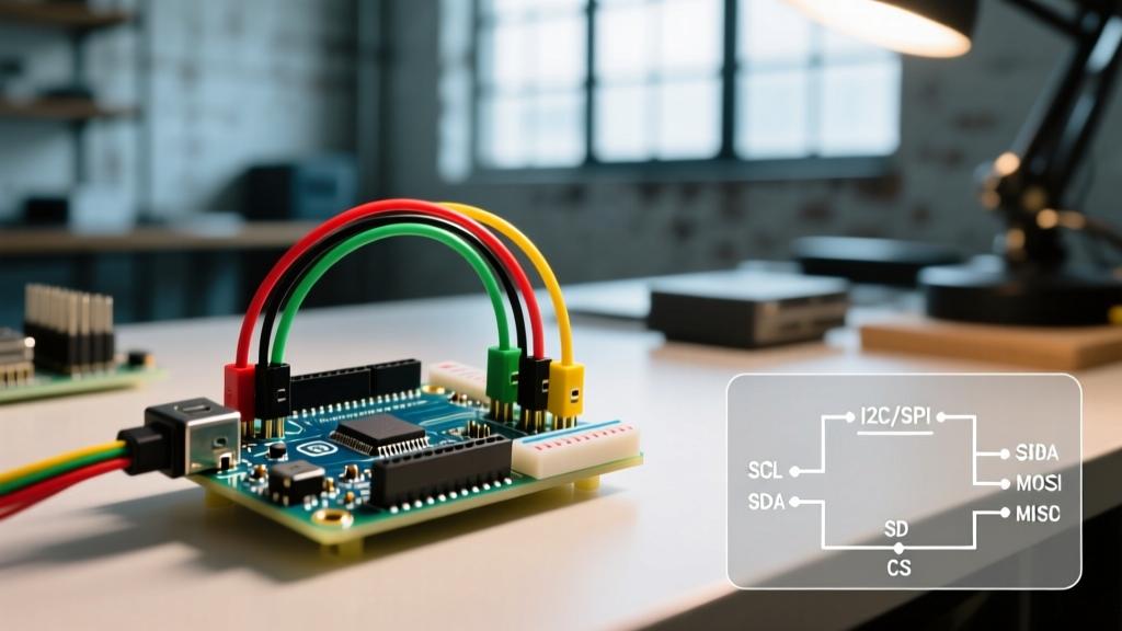
Bit-banging protocols in Linux user-space is a workflow killer due to the non-real-time nature of the OS. The Raspberry Pi 4 GPIO pinout exposes dedicated hardware peripherals that bypass the OS scheduler. Pins 3 (GPIO2) and 5 (GPIO3) are hardwired to the primary I2C bus. Crucially, these pins feature onboard 1.8k ohm pull-up resistors tied to the 3.3V rail. If your workflow involves connecting 5V I2C sensors, you cannot simply use a bidirectional logic level shifter without accounting for these onboard pull-ups, as the 5V device will backfeed current into the Pi's 3.3V system. Similarly, the primary UART pins (8 and 10, GPIO14/15) are multiplexed with the Bluetooth module on the BCM2711. To use these for reliable serial communication with an external microcontroller, you must explicitly disable the serial console in the OS configuration, otherwise, your external MCU will be flooded with Linux kernel boot logs.
Workflow Optimization 1: Software-to-Hardware Pin Mapping Frameworks
One of the most common sources of friction in embedded Linux development is the discrepancy between physical pin numbers and Broadcom (BCM) SoC pin numbers. Standardizing your team's workflow around a single numbering scheme eliminates an entire class of off-by-one wiring errors.
| Mapping Scheme | Reference Point | Workflow Impact & Best Use Case |
|---|---|---|
| BOARD | Physical Pin (1-40) | Best for rapid breadboarding and beginners. Highly prone to errors when migrating code to custom PCBs where physical layout changes. |
| BCM | Broadcom SoC GPIO (0-27) | The industry standard for production. Aligns directly with device tree overlays and kernel drivers. Mandatory for scalable workflows. |
| WiringPi | Legacy Custom Mapping | Deprecated and abandoned. Avoid entirely to prevent severe technical debt and compatibility issues with modern 64-bit OS builds. |
For optimized, long-term maintainability, mandate the BCM scheme across all Python (RPi.GPIO / gpiozero) and C++ (pigpio) codebases. When documenting your wiring diagrams, always label the BCM GPIO number prominently, as this is the universal language of the Raspberry Pi device tree.
Workflow Optimization 2: Designing Foolproof Custom Ribbon Cables
Spaghetti wiring on a breadboard is the enemy of reproducible testing. A highly effective workflow optimization is the creation of application-specific IDC (Insulation Displacement Connector) ribbon cables. By analyzing the Raspberry Pi 4 GPIO pinout, you can design a custom 40-pin cable that intentionally omits dangerous connections. For example, if you are building a sensor array that only requires 3.3V logic, you can physically sever the traces on your custom PCB that connect to pins 2 and 4 (the 5V rail). This hardware-level mistake-proofing (Poka-Yoke) ensures that even if a junior technician plugs a module in backward or misaligns a connector, a catastrophic 5V injection into a 3.3V input is physically impossible.
Avoiding Fatal Hardware Faults: The 3.3V Logic Trap
The most expensive mistake in a Pi-based workflow is treating the GPIO header like an Arduino. The Raspberry Pi 4 operates strictly at 3.3V logic levels. The BCM2711 SoC is not 5V tolerant. Applying 5V to any GPIO pin will instantly and permanently destroy the SoC's pad ring, often taking the entire board with it. When integrating legacy 5V maker components (like standard HC-SR04 ultrasonic sensors or older Adafruit displays) into your workflow, you must integrate a logic level translation step. While cheap BSS138 MOSFET-based shifters work for slow I2C, they often fail at high-speed SPI or UART baud rates due to gate capacitance. For high-speed workflows, invest in active logic level shifters like the TI SN74LVC8T245, which provide the necessary drive strength and propagation speed to maintain signal integrity without bottlenecking your data pipeline.
Accelerating Prototyping with Pi 4 HAT Standards
The Hardware Attached on Top (HAT) standard is a massive workflow accelerator. The Raspberry Pi 4 GPIO pinout reserves pins 27 (GPIO0) and 28 (GPIO1) specifically for an I2C EEPROM. When a compliant HAT is attached, the Pi reads this EEPROM during the early boot sequence and automatically configures the necessary GPIO directions, pull-up/pull-down states, and device tree overlays. By designing your custom peripheral boards to the HAT specification—including the EEPROM and ID pins—you eliminate the need for manual software configuration scripts. Your hardware becomes truly plug-and-play, allowing you to deploy units in the field without requiring an engineer to manually run setup scripts via SSH.
Summary Checklist for Rapid GPIO Deployment
Before applying power to your Raspberry Pi 4 prototype, run through this workflow checklist to ensure hardware and software alignment:
- Voltage Verification: Confirm all external modules operate at 3.3V or have appropriate active level shifters installed. Verify the 5V rail is not backfeeding the 3.3V rail.
- Peripheral Conflicts: Check if your chosen GPIOs conflict with default system functions (e.g., avoid GPIO14/15 for standard UART unless the serial console is disabled via raspi-config).
- Current Draw Calculation: Ensure the total current draw on the 3.3V pins (1 and 17) does not exceed 50mA to prevent onboard regulator thermal throttling.
- Pull-Up/Pull-Down State: Verify if your sensors require external pull resistors, or if the Pi's internal 50k ohm software-configurable resistors are sufficient for your noise environment.
- Resource Mapping: Cross-reference your physical wiring diagram against an authoritative visual guide like Pinout.xyz to catch alternate-function multiplexing errors before compiling your code.
By internalizing the electrical realities of the Raspberry Pi 4 GPIO pinout and embedding these checks into your standard operating procedures, you transform hardware integration from a chaotic troubleshooting exercise into a predictable, optimized engineering workflow.