
The Anatomy of a Reliable Push Button LED Arduino Circuit
Configuring a push button LED Arduino project seems trivial until you encounter floating inputs and mechanical switch bounce. While a basic sketch might toggle an LED erratically, a production-grade microcontroller configuration requires precise hardware wiring and non-blocking software debouncing. This guide details the exact configuration steps, component values, and edge-case troubleshooting required to build a robust input system in 2026.
Hardware Configuration: Solving the Floating Pin Problem
The most common failure mode in beginner MCU projects is the floating pin. When a tactile switch (like the standard 6x6x5mm thru-hole tact switch) is open, the microcontroller's input pin is disconnected from both VCC and GND. In this high-impedance state, the pin acts as an antenna, picking up electromagnetic interference (EMI) and causing the LED to flicker randomly.
Pull-Down vs. Internal Pull-Up Configuration
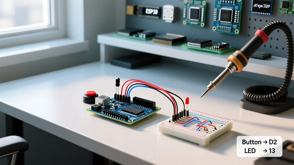
Historically, makers used an external 10kΩ pull-down resistor to tie the pin to GND. However, modern AVR and ARM-based boards (including the Uno R4 and Nano ESP32) feature built-in pull-up resistors. Utilizing the INPUT_PULLUP configuration eliminates the need for external resistors, reducing BOM costs and breadboard clutter.
| Configuration Type | Wiring Topology | Logic State (Open) | Logic State (Pressed) | Component Count |
|---|---|---|---|---|
| External Pull-Down | Pin to Switch, Switch to 5V. 10kΩ from Pin to GND. | LOW (0V) | HIGH (5V) | 2 (Switch + Resistor) |
| Internal Pull-Up | Pin to Switch, Switch to GND. | HIGH (5V) | LOW (0V) | 1 (Switch only) |
According to the official Arduino pinMode() documentation, activating the internal pull-up connects a 20kΩ to 50kΩ resistor to the VCC rail inside the silicon. For a push button LED Arduino setup, wiring the switch between the digital pin and GND is the undisputed best practice.
Tackling Switch Bounce: The 50-Millisecond Rule
Mechanical switches do not make a clean electrical connection. When the metal contacts close, they physically bounce, creating a rapid series of HIGH/LOW transitions lasting anywhere from 1 to 50 milliseconds. If your code reads the pin during this window, a single press will register as multiple toggles, causing your LED to turn on and off unpredictably.
Hardware Debouncing (RC Filter)
For environments with high EMI or when using long wire runs (over 1 meter), software debouncing is not enough. You must filter the noise at the hardware level. Place a 100nF (0.1µF) ceramic capacitor in parallel with the switch. Combined with a 10kΩ series resistor, this creates a low-pass filter with a time constant of 1ms, effectively smoothing out the microsecond contact arcing.
Software Debouncing (Non-Blocking)
Using delay(50) to wait out the bounce is a critical anti-pattern that halts your MCU. Instead, use a timestamp-based approach. The Arduino Debounce Example demonstrates tracking the lastDebounceTime. If the current time minus the last transition time exceeds 50ms, the state change is validated.
Expert Insight: In 2026, with MCUs running at clock speeds exceeding 480MHz (like the Raspberry Pi Pico 2 or ESP32-S3), software polling loops execute so fast that they can capture sub-millisecond EMI spikes. Always pair software debouncing with a 100nF bypass capacitor on the breadboard power rails to stabilize the VCC reference.
State-Change Detection vs. Level Triggering
A frequent logic error is using level triggering (checking if the button is currently LOW) to toggle an LED. This causes the LED to toggle hundreds of times per second while the button is held down. You must configure your sketch for edge triggering—specifically, detecting the exact moment the pin transitions from HIGH to LOW.
- Previous State Tracking: Store the last known reading in a variable (
lastButtonState). - Edge Detection: Compare the current reading to the previous reading. Only execute the LED toggle logic if they differ AND the current reading is the pressed state.
- Memory Update: Always update the previous state variable at the very end of the loop.
Selecting the Right Switch Hardware for MCU Inputs
Not all switches are created equal. The physical construction of the switch dictates the severity of the bounce and the required debounce configuration.
- Standard Tactile Switches (6x6mm): Costing roughly $0.05 each in bulk, these use a snap-action metal dome. They exhibit moderate bounce (5-15ms) and are rated for 100,000 cycles. Ideal for standard push button LED Arduino projects.
- Sealed Industrial Pushbuttons (e.g., Schneider XB4): Priced between $15 and $30, these heavy-duty switches feature robust mechanical linkages. Bounce times can exceed 25ms due to the larger mass of the contacts. Require a 75ms software debounce window.
- Piezo Switches: Costing $10-$20, these solid-state switches use a piezoelectric crystal to generate a voltage pulse. They have zero mechanical bounce but output a brief pulse rather than a sustained latching state, requiring interrupt-driven code to capture the transient signal.
Power Consumption: Pull-Ups in Deep Sleep Configurations
When designing battery-powered IoT nodes, the configuration of your push button LED Arduino circuit drastically impacts battery life. If a pin is configured as INPUT_PULLUP and the button is pressed (connecting the pin to GND), current flows continuously through the internal 20kΩ resistor. At 5V, this draws 250µA. While negligible for a USB-powered desk toy, this will drain a CR2032 coin cell in a matter of weeks if the button is jammed.
Expert Configuration: For ultra-low-power designs, disable internal pull-ups before entering deep sleep. Instead, use an external 1MΩ pull-up resistor combined with a hardware interrupt to wake the MCU. This reduces the static current draw to less than 5µA while maintaining a reliable logic HIGH state.
Real-World Failure Modes & Troubleshooting Matrix
| Symptom | Root Cause | Configuration Fix |
|---|---|---|
| LED toggles randomly without pressing | Floating pin or EMI coupling | Verify INPUT_PULLUP is set. Add 100nF cap across switch pins. |
| LED toggles 2-3 times per single press | Mechanical contact bounce | Increase software debounce window from 50ms to 100ms. |
| LED toggles while holding the button | Level triggering used instead of edge | Implement state-change detection logic (compare current vs. last state). |
| Button works on USB, fails on battery | Voltage drop / Brownout | Check 3.3V/5V rail under load. Ensure tactile switch is not bridging power rails. |
Frequently Asked Questions
Can I use a push button on an analog pin?
Yes. On standard AVR boards like the Uno, analog pins A0-A5 can be configured as digital I/O. Simply use pin numbers 14 through 19, or the A0 constant in your pinMode() configuration. This is highly useful when digital pins 2-12 are exhausted by LED matrices or sensor arrays.
Do capacitive touch buttons require debouncing?
Capacitive sensors (like the TTP223 module) output a clean digital signal and do not suffer from mechanical bounce. However, they can trigger falsely due to water droplets or extreme humidity. Configuring a 20ms software filter is still recommended for environmental noise rejection.
What is the maximum wire length for a push button?
For unshielded wires using internal pull-ups, keep runs under 50cm to prevent the wire from acting as an antenna. For runs up to 3 meters, use a lower value external pull-up resistor (e.g., 4.7kΩ) to increase the current and overpower induced noise, or switch to an I2C GPIO expander like the MCP23017 located near the button.
For further reading on pull-up resistor sizing and current draw calculations, consult the SparkFun pull-up resistor tutorial, which provides excellent mathematical models for varying wire capacitances.