
The Physics of Microcontroller Audio Generation
When makers first explore arduino music projects, they often assume that generating audio requires complex, dedicated sound chips. In reality, microcontrollers create sound by rapidly toggling digital pins to manipulate voltage over time. The quality, fidelity, and complexity of the resulting audio depend entirely on how the microcontroller's hardware timers and communication protocols are leveraged.
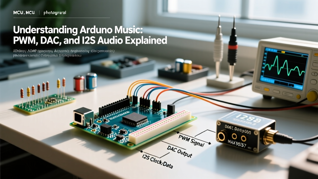
At its core, audio is simply an alternating current (AC) signal oscillating between 20 Hz and 20,000 Hz. A microcontroller operates on direct current (DC) logic levels (typically 0V and 5V or 3.3V). To bridge this gap, we use techniques like Pulse Width Modulation (PWM), Digital-to-Analog Conversion (DAC), and the Inter-IC Sound (I2S) protocol to synthesize waveforms that analog speakers can reproduce.
Square Waves vs. Sine Waves
The simplest audio signal a digital pin can produce is a square wave. By toggling a pin HIGH and LOW at a specific frequency (e.g., 440 Hz for an A4 note), you generate a tone. However, according to Fourier analysis, a square wave is composed of a fundamental sine wave plus an infinite series of odd harmonics. This is why basic microcontroller buzzers sound harsh and "chiptune-like" compared to the smooth sine waves produced by analog synthesizers.
Tier 1: The tone() Function (Basic Arduino Music)
The most accessible entry point for arduino music is the built-in Arduino tone() function. This function configures one of the ATmega328P's hardware timers to output a 50% duty cycle square wave on a specified pin.
⚠️ Hardware Conflict Warning: On the Arduino Uno R3, thetone()function relies on Timer2. If you calltone(), it will disable PWM functionality (viaanalogWrite()) on Pins 3 and 11 untilnoTone()is called. Always plan your pinouts accordingly to avoid breaking motor controls or LED fades.
While excellent for simple UI beeps, alarms, and basic monophonic melodies, the tone() function cannot play polyphonic audio, sampled WAV files, or complex synthesized waveforms. It is strictly limited to single-frequency square waves.
Tier 2: PWM Audio and RC Low-Pass Filtering
To generate complex waveforms (like sine, triangle, or sawtooth waves) without external hardware, you can use Direct Digital Synthesis (DDS) via PWM. By changing the duty cycle of a high-frequency PWM signal thousands of times per second, you can "sculpt" an analog waveform.
Designing the RC Low-Pass Filter
The raw PWM signal contains the desired audio frequencies mixed with the high-frequency PWM carrier noise. To extract the audio, you must pass the signal through an RC (Resistor-Capacitor) low-pass filter.
- Carrier Frequency: Configure Timer1 to run at 62.5 kHz (Phase Correct PWM, no prescaler on a 16 MHz clock).
- Cutoff Frequency: According to the Nyquist-Shannon sampling theorem, your audio sample rate must be at least twice the highest audio frequency. For a 16 kHz audio bandwidth, a cutoff of ~15.9 kHz is ideal.
- Component Values: Using the formula
fc = 1 / (2πRC), a 1 kΩ resistor and a 10 nF ceramic capacitor yield a cutoff frequency of approximately 15.9 kHz, effectively smoothing the 62.5 kHz carrier into an analog voltage.
Tier 3: External DACs and the Mozzi Library
For makers seeking richer arduino music synthesis—such as FM synthesis, granular delay, or wavetable oscillators—the Mozzi audio library is the industry standard for 8-bit AVRs. Mozzi hijacks Timer1 to output 16,384 Hz audio samples using high-speed PWM on Pins 9 and 10 in a differential configuration, effectively doubling the signal-to-noise ratio.
Upgrading to True I2C DACs
If PWM filtering introduces too much noise for your application, you can offload digital-to-analog conversion to an external IC like the MCP4725. Connected via I2C, this 12-bit DAC provides clean voltage outputs. However, the I2C bus speed (typically 400 kHz) limits the maximum sample rate to roughly 30-40 kHz, which is sufficient for voice and basic music but struggles with high-fidelity stereo audio.
| Audio Method | Hardware Required | Max Sample Rate | Typical Cost (2026) | Best Use Case |
|---|---|---|---|---|
tone() Square Wave | Passive Buzzer | N/A (Single Freq) | $0.50 | Alarms, simple melodies |
| PWM + RC Filter | 1kΩ Resistor, 10nF Cap | ~16 kHz | $0.10 | Sampled speech, basic WAV |
| Mozzi (Differential PWM) | Audio Amp (PAM8403) | 16.384 kHz | $2.50 | FM Synthesis, sound effects |
| I2C DAC (MCP4725) | MCP4725 Breakout | ~35 kHz | $4.00 | Control voltages, clean sine |
| I2S Protocol | MAX98357A Amp | 44.1 kHz - 96 kHz | $6.50 | Hi-Fi music, polyphonic WAV |
Tier 4: I2S Protocol for High-Fidelity Arduino Music
As of 2026, the gold standard for microcontroller audio is the I2S (Inter-IC Sound) protocol. Unlike I2C or SPI, I2S is specifically designed for digital audio. It separates the clock signal from the data signal, eliminating the timing jitter that plagues PWM-based audio generation.
I2S requires three primary connections:
- BCLK (Bit Clock): Synchronizes the transmission of each individual bit.
- LRCLK (Left/Right Clock or Word Select): Dictates the sample rate and switches between stereo channels.
- DIN (Serial Data): The actual 16-bit or 24-bit audio payload.
The ESP32 Advantage
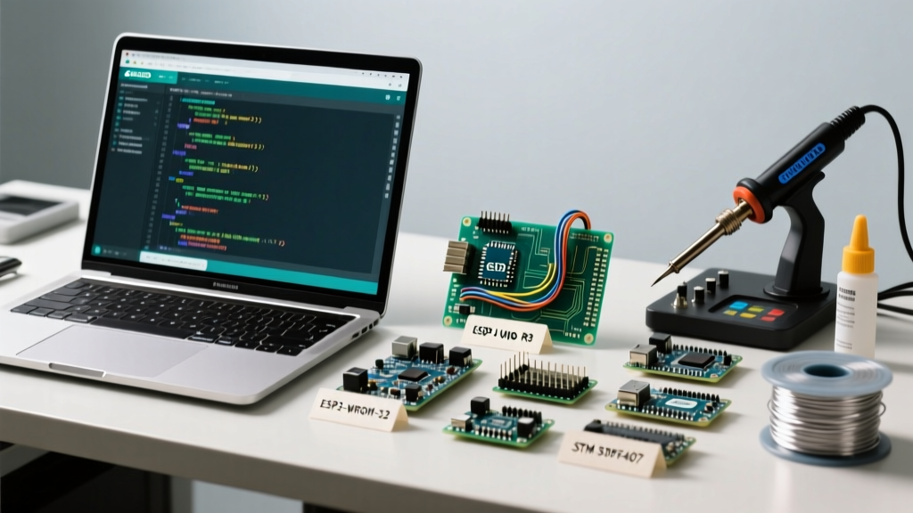
While the Arduino Nano 33 BLE Sense supports I2S, the ESP32-WROOM-32 (and newer ESP32-S3 variants) remain the undisputed champions of arduino music projects. The ESP32 features a dedicated I2S peripheral connected to a DMA (Direct Memory Access) controller. This allows the MCU to stream audio buffers directly from Flash or RAM to the I2S amplifier without burdening the main CPU cores, ensuring zero audio dropouts even while running Wi-Fi or Bluetooth stacks.
Hardware BOM: Building an I2S Audio Player
To build a high-fidelity I2S audio player, you need an I2S amplifier breakout. The Adafruit MAX98357A I2S Class-D Mono Amp is the most reliable choice on the market. It includes the necessary DAC and amplifier in a single 3.2mm x 3.2mm QFN package, capable of delivering 3.2W into a 4Ω speaker.
Wiring the MAX98357A to an ESP32
- VIN: Connect to 5V (Do not use 3.3V; the amp requires 5V for full power output).
- GND: Connect to common ground.
- BCLK: Connect to ESP32 GPIO 26.
- LRC (LRCLK): Connect to ESP32 GPIO 25.
- DIN: Connect to ESP32 GPIO 22.
- GAIN: Leave unconnected for 15dB gain, or bridge to GND for 9dB if your audio source clips.
Troubleshooting Common Audio Artifacts
Even with perfect code, hardware-level physics can introduce unwanted noise into your arduino music projects. Here is how to diagnose and fix the most common edge cases:
1. Ground Loop Hum (50/60 Hz Buzz)
If your speaker emits a low-frequency hum, you likely have a ground loop caused by sharing power rails between high-current digital components (like LED matrices or motors) and your audio amplifier. Fix: Implement "star grounding." Run a dedicated ground wire from the power supply directly to the audio amplifier's GND pin, bypassing the microcontroller's ground rail entirely.
2. High-Frequency Whine (Aliasing)
A piercing, metallic whine usually indicates aliasing—high-frequency noise folding back into the audible spectrum because the sample rate is too low or the anti-aliasing filter is missing. Fix: Ensure your software sample rate is at least 44.1 kHz for I2S, and if using PWM, verify your RC filter capacitor hasn't degraded (ceramic capacitors can lose up to 50% capacitance under DC bias).
3. Audio Stuttering and Buffer Underruns
If your WAV playback stutters, the microcontroller's CPU is failing to fill the audio buffer before the DMA reads it. Fix: On the ESP32, increase the I2S DMA buffer count from 4 to 8 in your configuration struct, and ensure you are reading audio data from internal SRAM rather than fetching directly from SPIFFS/LittleFS on every audio tick.
By understanding the progression from basic square waves to DMA-driven I2S streams, you can select the exact audio architecture required for your next embedded project, balancing cost, fidelity, and processing overhead.