
The Evolution of the Arduino Robotic Arm 3D Print Community
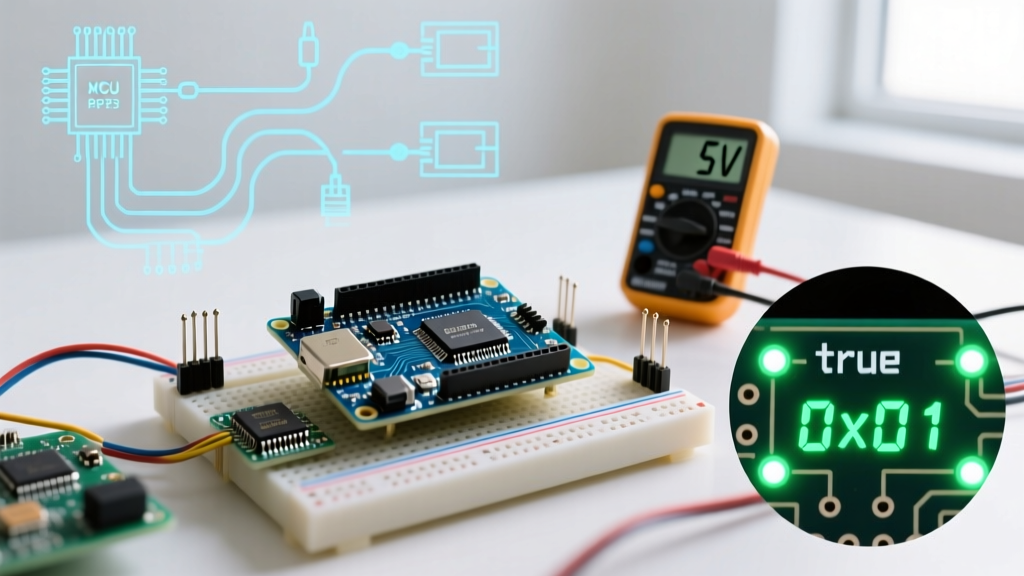
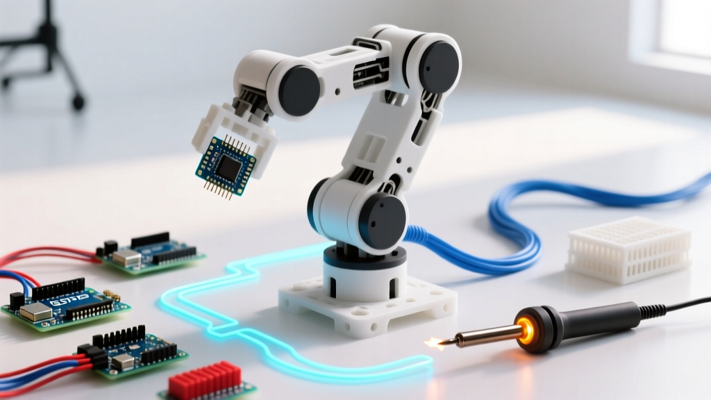
Building an arduino robotic arm 3d print project has evolved dramatically over the last few years. What started as fragile, low-tolerance PLA toys powered by micro-servos has matured into a robust ecosystem of desktop automation, capable of light manufacturing, PCB pick-and-place, and advanced computer vision tasks. In 2026, the maker community has shifted focus toward higher payload capacities, closed-loop stepper systems, and advanced inverse kinematics. This roundup synthesizes the most reliable open-source designs, hardware configurations, and failure-mode troubleshooting strategies for makers looking to build a functional, high-precision robotic arm.
Community Design Comparison Matrix
Choosing the right baseline architecture is critical. Below is a comparison of the three most prominent open-source archetypes dominating the arduino robotic arm 3d print space this year.
| Project Archetype | DOF & Actuation | Estimated BOM Cost (2026) | Payload Capacity | Best Use Case |
|---|---|---|---|---|
| MeArm (Classic/V2) | 4-DOF, SG90 Micro Servos | $25 - $35 | ~50 grams | Education, basic sorting, introductory kinematics |
| EEZYbotARM MK3 | 4-DOF, MG996R Metal Gear | $80 - $110 | ~500 grams | Desktop pick-and-place, camera gimbals |
| BCN3D Moveo / Custom NEMA | 5-DOF + Gripper, NEMA 17 Steppers | $250 - $350 | ~1.5 kg | PCB assembly, 3D printing toolheads, ROS 2 integration |
Expert Insight: If your goal is precise repeatability (under 0.5mm variance), abandon standard hobby servos immediately. The potentiometer-based feedback in an MG996R degrades over time, leading to positional drift. Opt for NEMA 17 steppers with planetary gearboxes or closed-loop servos like the Lichuan A1.
Microcontroller Selection for Inverse Kinematics
While the classic Arduino Uno R3 can handle basic joint-angle mapping, it chokes on real-time inverse kinematics (IK) calculations. The floating-point math required to translate Cartesian (X, Y, Z) coordinates into joint angles via Jacobian matrices requires a more capable MCU.
Top MCU Recommendations for 2026
- Arduino Uno R4 Minima ($27.50): Features a 32-bit Arm Cortex-M4. It handles basic IK and trapezoidal motion profiling smoothly, making it the best drop-in upgrade for legacy shields.
- ESP32-S3 ($8 - $12): The community favorite for wireless-enabled arms. Its dual-core architecture allows one core to handle Wi-Fi/Bluetooth communication (e.g., receiving ROS 2 commands) while the dedicated core handles high-frequency PWM generation for servos via the LEDC peripheral.
- Teensy 4.1 ($34.99): Running at 600 MHz, this is the undisputed king for complex, multi-axis motion control. If you are running a 6-DOF arm with real-time trajectory planning and dynamic obstacle avoidance, the Teensy's floating-point unit (FPU) is mandatory.
Power Architecture & Servo Jitter Troubleshooting
The most common point of failure in any arduino robotic arm 3d print build is power brownout. Makers frequently wire MG996R servos directly to the Arduino 5V pin, resulting in catastrophic MCU resets and erratic joint spasms.
The Physics of Servo Stall Current
A standard MG996R servo draws roughly 500mA during normal operation, but its stall current can spike to 2.5A. If your arm has four servos and two stall simultaneously under load, your power supply must instantly deliver 5A without the voltage dropping below 4.8V. The Arduino onboard regulator maxes out around 800mA and will thermally throttle or fail.
The Bulletproof Power Wiring Standard
- Power Supply: Use a dedicated 5V 10A (50W) switching power supply (e.g., Mean Well RS-50-5, approx. $18).
- Distribution: Wire the 5V and GND directly to a heavy-gauge terminal block or custom PCB bus bar.
- Common Ground: You must connect the GND of the 5V servo supply to the GND of the Arduino/ESP32. Without a common ground reference, the PWM signal will float, causing violent servo jitter.
- Decoupling: Solder a 1000µF electrolytic capacitor and a 0.1µF ceramic capacitor across the power rails at the terminal block to absorb transient voltage spikes during rapid direction changes.
3D Printing Tolerances & Material Science
A robotic arm is only as rigid as its joints. Printing an arm in standard PLA is a recipe for failure; PLA exhibits severe cold creep under constant static loads, meaning a joint holding a 200g weight will slowly deform and lose positional accuracy over a few hours.
Material Selection Guide
- PETG ($20 - $25/kg): The baseline requirement. Offers excellent layer adhesion and slight flexibility, which prevents brittle snapping under sudden inertial loads. Requires 0.15mm to 0.2mm clearance for M3/M4 bolt holes.
- ABS / ASA ($25 - $35/kg): Mandatory for the base and shoulder joints. ASA provides UV resistance and higher thermal deflection. You can also use acetone vapor smoothing to increase the compressive strength of the joints by up to 15%.
- Polycarbonate (PC) / Carbon-Fiber Nylon ($60+/kg): Used in high-end community builds for the end-effector and wrist joints where weight reduction and extreme rigidity are paramount.
Slicer Settings for Load-Bearing Joints
Do not rely on high infill percentages for strength; rely on perimeters (walls). Set your slicer to 4-5 perimeters (approx. 1.6mm - 2.0mm wall thickness) with a 20% Gyroid infill. Gyroid provides isotropic strength and prevents the infill from interfering with the inner wall extrusion paths. Use a minimum of 3 top/bottom solid layers to ensure bearing surfaces don't collapse under axial loads.
End-Effector Upgrades & Integration
The standard 3D-printed claw gripper is rarely sufficient for practical automation. The community has standardized around two modular end-effector upgrades:
- Vacuum Pick-and-Place: Utilizing a 12V micro-diaphragm vacuum pump paired with a silicone suction cup. Control is achieved via an N-channel MOSFET (like the IRLZ44N) triggered by a digital pin. This is the gold standard for moving PCBs, glass slides, or flat components.
- Electromagnetic Tool Changers: Inspired by industrial SCARA robots, makers are embedding 12V electromagnets into the wrist joint, allowing the arm to automatically swap between a pen plotter, a soldering iron tip, or a camera module.
Software Stacks & Kinematics Libraries
To bring your hardware to life, you need robust motion planning. The days of using the standard Arduino Servo Library for complex arms are over; its blocking delays and lack of acceleration profiles cause mechanical shaking.
Recommended Firmware & Libraries
- VarSpeedServo: A drop-in replacement for the standard servo library that allows you to define movement speed, enabling smooth, coordinated joint transitions without complex math.
- AccelStepper: Essential for NEMA 17 builds. It handles trapezoidal acceleration and deceleration curves, preventing the stepper motors from losing steps during high-speed directional changes.
- GRBL / FluidNC: For Cartesian and SCARA configurations, adapting GRBL (or its modern ESP32 fork, FluidNC) allows you to control the arm using standard G-code, making it compatible with existing CNC software and CAD/CAM pipelines.
Community Repositories & Sourcing
When sourcing STL files, avoid outdated legacy repositories. Platforms like Printables and Thangs currently host the most actively maintained, parametric CAD files (STEP/IGES) alongside STLs. Having the STEP files is crucial; it allows you to modify the motor mounts in Fusion 360 or FreeCAD to accommodate alternative actuators or custom sensor brackets without having to reverse-engineer the mesh geometry.
Building a high-quality arduino robotic arm 3d print system in 2026 is less about the 3D printing itself and more about the integration of rigid mechanical design, high-current power distribution, and advanced motion-control firmware. By selecting the right MCU, respecting servo stall currents, and utilizing engineering-grade filaments, your desktop robot will transition from a weekend novelty to a reliable automation tool.