
The Anatomy of a Failing Push Button Arduino Circuit
Wiring a tactile switch to a microcontroller seems like the most fundamental task in embedded electronics. Yet, the "push button Arduino" setup remains one of the most frequent sources of frustration for makers and engineers alike. You upload a simple digitalRead() sketch, press the button once, and the serial monitor spams fifty HIGH and LOW transitions. Alternatively, the pin triggers randomly when you are not even touching the switch.
These issues are rarely caused by defective microcontrollers. Instead, they stem from two fundamental physics and engineering realities: floating high-impedance pins and mechanical switch bounce. This guide provides a definitive, component-level troubleshooting framework to diagnose and permanently fix your push button circuits, whether you are using a classic AVR-based Uno R4, a Nano Every, or an ESP32-S3.
Phase 1: Diagnosing the "Floating Pin" Phenomenon
If your Arduino registers random button presses without any physical input, you are dealing with a floating pin. When a GPIO pin is configured as an INPUT but is not physically connected to VCC (5V/3.3V) or GND, it enters a high-impedance state. In this state, the pin acts as an antenna, picking up ambient electromagnetic interference (EMI), 50/60Hz mains hum from nearby power cables, and even static electricity from your body.
The Hardware Fix: Pull-Up and Pull-Down Resistors
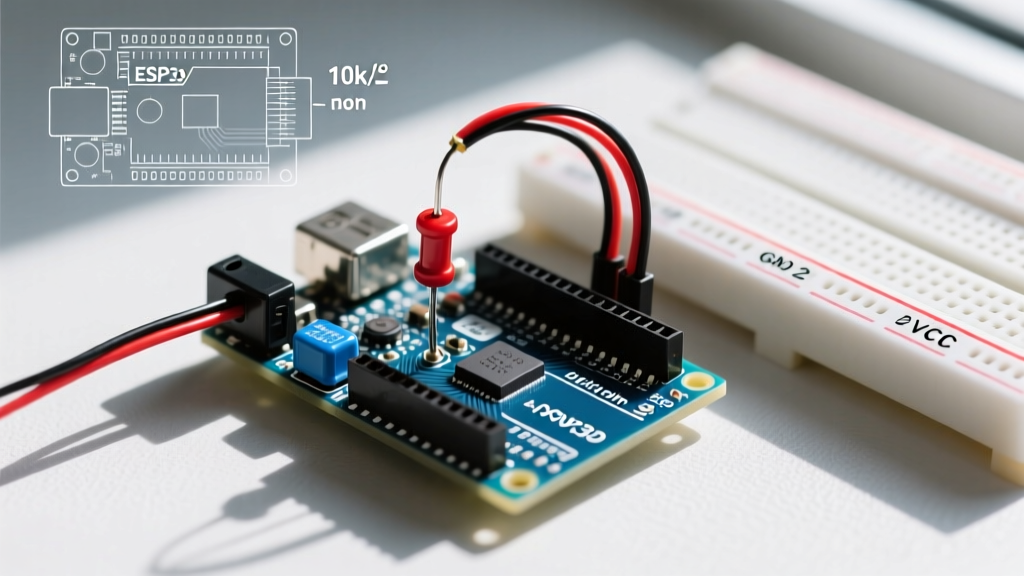
To anchor the pin to a known voltage state, you must use a resistor. According to the SparkFun tutorial on pull-up resistors, a standard value of 10kΩ is ideal for most 5V and 3.3V logic systems. It provides enough current to overpower ambient noise while keeping power consumption low (only 0.5mA at 5V).
- Pull-Up Configuration (Recommended): Wire the switch between the GPIO pin and GND. The resistor connects the GPIO pin to VCC. When unpressed, the pin reads HIGH. When pressed, it reads LOW.
- Pull-Down Configuration: Wire the switch between the GPIO pin and VCC. The resistor connects the GPIO pin to GND. When unpressed, the pin reads LOW. When pressed, it reads HIGH.
The Software Fix: Internal Pull-Ups
Modern microcontrollers include internal pull-up resistors, saving you from soldering external components. As documented in the official Arduino pinMode() reference, you can activate this by changing your setup code:
// Incorrect: Leaves pin floating if no external resistor is used
pinMode(2, INPUT);

// Correct: Activates internal 20kΩ - 50kΩ pull-up resistor
pinMode(2, INPUT_PULLUP);
⚠️ CRITICAL ESP32 GOTCHA: If you are migrating from an ATmega328P (Uno/Nano) to an original ESP32 (WROOM-32), be aware that GPIO pins 34, 35, 36, and 39 are input-only and do not have internal pull-up resistors. You must use external 10kΩ pull-up resistors on these specific pins, or your push button Arduino circuit will fail unpredictably.
Phase 2: Taming Mechanical Switch Bounce
If your serial monitor shows a single button press registering as 10 to 50 rapid transitions, you are experiencing switch bounce. Inside a standard tactile switch (like the ubiquitous 6x6mm Omron B3F series), a metal dome makes contact with the PCB pads. When the dome snaps into place, it physically bounces microscopically for 1 to 5 milliseconds before settling. The Arduino, executing millions of instructions per second, reads every single microscopic bounce as a distinct button press.
Hardware Debouncing: The RC Filter
For mission-critical applications where software latency is unacceptable, use an RC (Resistor-Capacitor) low-pass filter. By placing a 100nF (0.1µF) ceramic capacitor in parallel with the switch (between the GPIO pin and GND), you create a time delay that absorbs the mechanical bounce.
The time constant ($\tau$) is calculated as $R \times C$. With a 10kΩ pull-up and a 100nF capacitor, $\tau = 1ms$. This smoothly filters out the high-frequency bounce spikes while allowing the deliberate human press to pass through to the GPIO pin.
Software Debouncing: The Non-Blocking Approach
The most common beginner mistake is using delay(50) to wait out the bounce. This blocks the main loop, halting LEDs, motor control, and sensor reading. Instead, use a state-machine approach with millis(). For complex projects with multiple buttons, the widely adopted Bounce2 library by Thomas Ouellet Fredericks is the industry standard for Arduino environments.
Here is a robust, non-blocking debounce implementation using native C++:
const int buttonPin = 2;
int buttonState;
int lastReading = HIGH;
unsigned long lastDebounceTime = 0;
const unsigned long debounceDelay = 50; // 50ms debounce window

void setup() {
  pinMode(buttonPin, INPUT_PULLUP);
  Serial.begin(115200);
}

void loop() {
  int currentReading = digitalRead(buttonPin);

  if (currentReading != lastReading) {
    lastDebounceTime = millis(); // Reset timer on state change
  }

  if ((millis() - lastDebounceTime) > debounceDelay) {
    if (currentReading != buttonState) {
      buttonState = currentReading;
      // Only trigger on the exact moment of a stable LOW (pressed)
      if (buttonState == LOW) {
        Serial.println("Button Pressed (Debounced)");
      }
    }
  }
  lastReading = currentReading;
}
Diagnostic Matrix: Push Button Arduino Troubleshooting
Use this table to quickly isolate the root cause of your specific failure mode.
| Symptom | Multimeter / Scope Reading | Root Cause | Engineer's Fix |
|---|---|---|---|
| Random triggers without pressing | Voltage fluctuating between 0.5V and 4.5V | Floating pin / Ambient EMI pickup | Enable INPUT_PULLUP or add external 10kΩ pull-up. |
| One press registers as 10-50 presses | Square wave with 1-5ms of jagged edges on scope | Mechanical switch bounce | Implement millis() software debounce or add 100nF capacitor. |
| Button works, but logic is inverted | Pin reads HIGH when pressed, LOW when released | Using external pull-down instead of pull-up | Invert logic in code: if (!digitalRead(pin)). |
| Fails only when motor turns on | Massive voltage spikes on VCC rail | Back-EMF from inductive loads coupling into signal wire | Add flyback diode to motor; use shielded/twisted pair for button wiring. |
| Intermittent connection when wiggling wires | Resistance jumps from 0Ω to >1kΩ randomly | Breadboard contact oxidation or 24AWG wire fatigue | Switch to 22AWG solid core wire; replace worn breadboard tie-points. |
Advanced Edge Cases: Long Wire Runs and Enclosure Integration
A circuit that works perfectly on a desktop breadboard often fails when installed in a final project enclosure. Why? Wire capacitance and resistance.
If you run wires longer than 1 meter (approx. 3 feet) from your push button to your Arduino, the wire itself develops parasitic capacitance and acts as a massive antenna. The internal 50kΩ pull-up resistor is too weak to quickly charge this capacitance, resulting in slow rising edges that the microcontroller misinterprets as noise.
The Long-Wire Solution
- Lower the Pull-Up Resistance: Drop the external pull-up resistor from 10kΩ to 4.7kΩ or even 1kΩ. This increases the current flow, allowing the wire capacitance to charge faster and overpower induced noise.
- Use Twisted Pair Wiring: Twist the signal wire and the GND wire together tightly. This ensures that any ambient magnetic interference induces equal and opposite voltages in the wires, effectively canceling out the noise (Common Mode Rejection).
- Opto-Isolation: For industrial environments or runs exceeding 5 meters, abandon direct GPIO wiring. Use an optocoupler (like the PC817) at the button end to transmit the signal via light, completely breaking the electrical ground loop.
Summary Checklist for Reliable Button Inputs
Before finalizing your PCB design or permanently soldering your enclosure, verify these four parameters:
- [ ] Pin mode is explicitly set to
INPUT_PULLUP(or external 10kΩ resistor is verified with a multimeter). - [ ] Logic is inverted in software to account for the pull-up configuration (LOW = Pressed).
- [ ] Software debounce is implemented using
millis()with a 50ms window, avoidingdelay(). - [ ] If using an ESP32, input pins are verified against the strapping pin and internal pull-up limitation charts.
By treating the push button Arduino circuit not just as a simple switch, but as an analog sensor subject to the laws of physics, you will eliminate ghost presses and build interfaces that feel instantaneous and rock-solid.