
The Hidden Bottlenecks in Standard RTC Workflows
Integrating a Real Time Clock (RTC) into an embedded project seems trivial on the surface: wire up four I2C pins, include a library, and call rtc.now(). However, as projects scale from simple dataloggers to complex, battery-operated IoT nodes, this naive approach quickly falls apart. Standard tutorials often ignore I2C bus contention, catastrophic battery drain edge cases, and blocking code architectures. When you optimize your rtc clock arduino workflow, you transition from merely 'getting the time' to engineering a robust, low-power temporal foundation.
In this guide, we will dissect the hardware selection process, expose a dangerous flaw in popular hobbyist modules, and restructure your software architecture to leverage hardware interrupts rather than inefficient polling.
Hardware Selection Matrix: DS1307 vs. DS3231 vs. PCF8523
Before writing a single line of code, your workflow must begin with selecting the right silicon. The market is flooded with legacy chips that will sabotage long-term deployment. Below is a comparative analysis of the three most common RTC ICs available to makers in 2026.
| RTC IC Model | Avg. Price (2026) | Timekeeping Accuracy | Core Architecture | Workflow Verdict |
|---|---|---|---|---|
| DS1307 | $1.50 - $2.50 | ±5 minutes/month | Standard Crystal Oscillator | Avoid. Temperature drift makes it useless for outdoor or precision logging. |
| DS3231 | $4.00 - $6.50 | ±2 ppm (±1 min/year) | TCXO (Temp Compensated) | Best Overall. Ideal for precision datalogging and environmental monitoring. |
| PCF8523 | $3.00 - $4.50 | ±20 ppm | Standard Crystal + Low Power | Best for Battery. Superior power-down modes for ultra-low-power sleep workflows. |
For the remainder of this guide, we will focus on the DS3231, as its Temperature-Compensated Crystal Oscillator (TCXO) provides the reliability required for professional-grade maker projects. For a deeper dive into the IC's internal registers, refer to the Adafruit DS3231 Precision Breakout Guide.
Critical Workflow Fix: The ZS-042 Module Battery Hazard
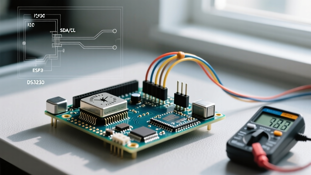
If you purchase a generic DS3231 module online, you will likely receive the blue ZS-042 breakout board. This board contains a severe design flaw that disrupts optimized workflows and poses a physical safety hazard.
⚠️ Expert Warning: The ZS-042 module includes a charging circuit designed for LIR2032 rechargeable lithium-ion cells (3.6V). It routes VCC through a 1N4148 diode and a 200Ω resistor to the battery holder. If you insert a standard, non-rechargeable CR2032 (3.0V), the module will attempt to charge it, leading to battery rupture, extreme heat, and destroyed PCB traces.
Optimizing the Hardware Preparation Step
To streamline your build process and ensure safety, you must modify the ZS-042 module before connecting it to your microcontroller. You have two workflow options:
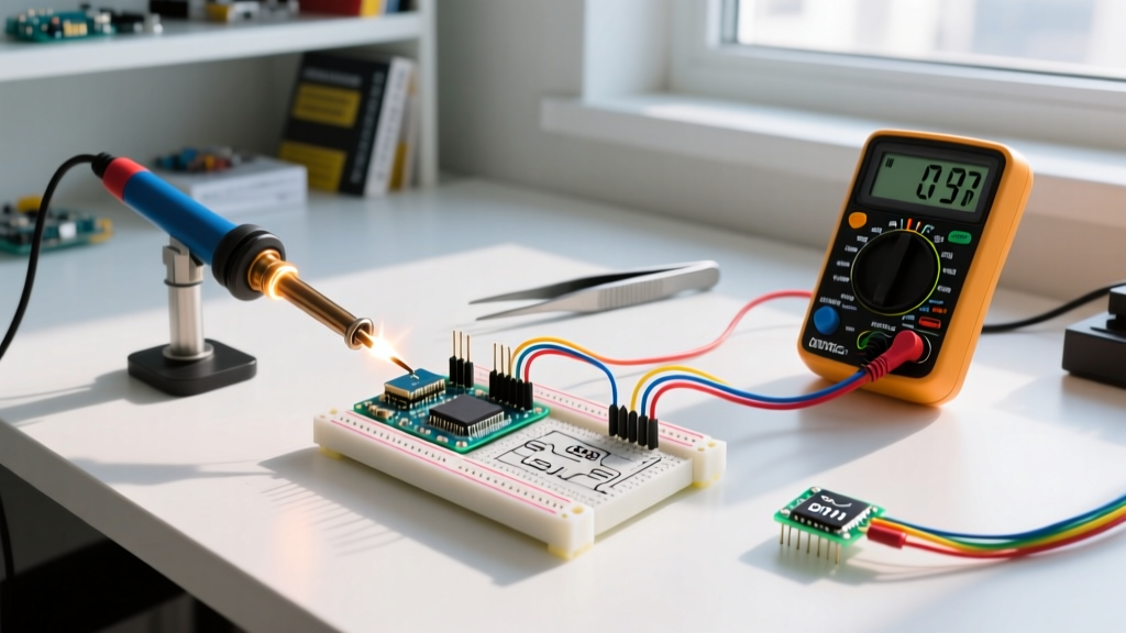
- The Desoldering Method: Use a soldering iron to remove the surface-mount diode (marked D1) or the 200Ω resistor near the battery holder. This permanently disables the charging circuit, making it safe for standard CR2032 cells.
- The Procurement Pivot: Bypass the ZS-042 entirely. Source minimal breakouts like the Adafruit 5188 or raw DS3231SN chips on SOP-8 adapter boards, which omit the flawed charging circuit and reduce the overall PCB footprint.
Streamlining I2C Wiring and Pull-Up Resistor Management
The DS3231 communicates via I2C at address 0x68. A common failure mode in complex Arduino workflows is I2C bus lockup, often caused by improper pull-up resistor configurations. Understanding the electrical characteristics of the Arduino Wire Library and I2C bus capacitance is vital.
The Pull-Up Resistor Math
Most DS3231 breakout boards include 4.7kΩ pull-up resistors on the SDA and SCL lines. If your project also includes an I2C OLED display or a BME280 sensor, those modules likely have their own pull-ups. Resistors in parallel reduce the total resistance.
- One 4.7kΩ resistor = 4.7kΩ (Current sink at 5V: ~1.06mA)
- Two 4.7kΩ resistors in parallel = 2.35kΩ (Current sink: ~2.12mA)
- Three 4.7kΩ resistors in parallel = 1.56kΩ (Current sink: ~3.2mA)
The standard I2C specification mandates a maximum sink current of 3mA. If you daisy-chain too many modules with onboard pull-ups, you violate this spec, resulting in corrupted time data or complete bus freezes. Workflow Rule: Always measure the combined pull-up resistance with a multimeter. If it drops below 2.2kΩ, scrape off the SMD pull-up resistors on the secondary modules using an X-Acto knife or hot air rework station. For a comprehensive primer on bus physics, consult the SparkFun I2C Tutorial.
Software Architecture: Non-Blocking Time Polling
Beginner sketches often rely on calling DateTime now = rtc.now(); at the very top of the loop() function. While functional, this creates a massive bottleneck. Querying the RTC requires multiple I2C transactions, taking roughly 1 to 2 milliseconds. If your loop runs thousands of times per second, you are monopolizing the I2C bus and wasting CPU cycles.
Implementing Throttled Time Checks
Optimize your software workflow by decoupling the RTC read cycle from the main execution loop. Use a millis() based timer to poll the RTC only when necessary (e.g., once per second or once per minute).
Conceptual Logic Flow:
- Define an
intervalvariable (e.g., 1000ms). - Store the
previousMillis. - Inside
loop(), check ifcurrentMillis - previousMillis >= interval. - Only execute
rtc.now()and update your global time variables inside this conditional block.
This ensures your microcontroller remains free to handle sensor readings, motor controls, and wireless transmissions without being bottlenecked by I2C latency.
Advanced Workflow: Triggering Sleep Modes via RTC Alarms
If your project is deployed in the field on battery power, keeping the ATmega328P (or ESP32) awake 24/7 is an inefficient use of energy. The DS3231 features a dedicated SQW/INT pin that can output a precise square wave or trigger a hardware interrupt based on internal alarms.
Step-by-Step Interrupt Integration
- Hardware Routing: Connect the DS3231 SQW pin to Arduino Digital Pin 2 (which maps to hardware interrupt
INT0). - Library Configuration: Use the
writeSqwPinMode(DS3231_OFF)function in Adafruit's RTClib to disable the square wave and enable the interrupt mode. - Set the Alarm: Configure Alarm 1 to trigger at a specific second, minute, or hour using
rtc.setAlarm1(). - ARM the Interrupt: Call
attachInterrupt(digitalPinToInterrupt(2), wakeUpRoutine, FALLING);in your setup. - Enter Sleep: Utilize the
avr/sleep.hlibrary to put the microcontroller intoPOWER_DOWNmode.
When the RTC alarm triggers, it pulls the SQW pin LOW, waking the Arduino instantly. After executing the required task (e.g., logging soil moisture), the sketch clears the RTC alarm flag via rtc.clearAlarm(1) and returns to sleep. This workflow can reduce average power consumption from 20mA down to microamps, extending a standard 2000mAh 18650 battery life from a few days to several months.
Summary of Workflow Best Practices
Mastering the rtc clock arduino integration is less about copying a wiring diagram and more about anticipating edge cases. By selecting the TCXO-equipped DS3231, neutralizing the ZS-042 charging hazard, managing I2C pull-up capacitance, and leveraging hardware alarms for sleep states, you elevate your project from a fragile prototype to a resilient, deployment-ready system. Always prioritize bus integrity and non-blocking code structures to ensure your temporal data remains accurate and your microcontroller resources remain optimized.