
The Evolution of I2C in Modern Maker Projects
For over a decade, the classic Arduino Uno R3 dictated the standard for hobbyist electronics. When makers needed to connect an OLED display, a BME280 sensor, or an EEPROM chip, they relied on the familiar A4 (SDA) and A5 (SCL) pins. However, as we navigate the hardware landscape of 2026, the ecosystem has shifted dramatically. Modern microcontrollers like the ESP32-S3, Raspberry Pi RP2350, and the Arduino Nano ESP32 operate at 3.3V logic levels, offer multiple I2C buses, and demand much stricter signal integrity.
Migrating your legacy 5V Arduino SCL SDA setups to modern, high-speed, 3.3V architectures is not as simple as swapping the development board. It requires a fundamental rethinking of logic level translation, bus capacitance management, and pull-up resistor calculations. This comprehensive migration guide will walk you through upgrading your I2C topology to ensure rock-solid communication in complex, multi-sensor environments.
The 5V to 3.3V Logic Level Migration
The most immediate hurdle when migrating from an ATmega328P-based Uno to a modern 3.3V MCU is logic level incompatibility. Feeding 5V from a legacy sensor's SDA line directly into an ESP32-S3's GPIO pin will fry the microcontroller's input buffer. Conversely, a 3.3V SCL signal from an RP2350 might not reliably trigger the logic-high threshold of a 5V legacy sensor.
Choosing the Right Level Shifter
Not all level shifters are created equal. The market is flooded with cheap, generic BSS138 MOSFET-based bi-directional logic level converters (typically priced around $1.50). While these work adequately for Standard Mode (100 kHz) I2C, they often fail catastrophically at Fast Mode (400 kHz) or Fast Mode Plus (1 MHz) due to the high gate capacitance of the MOSFETs, which rounds off the sharp edges of the SCL clock signal.
For a robust 2026 upgrade, migrate to active level shifters like the PCA9306 or TXB0108. A breakout board featuring the PCA9306 (such as the Adafruit or SparkFun variants, retailing for approximately $4.50) includes internal pull-up current sources and active edge acceleration. This ensures crisp, square waveforms on both the SCL and SDA lines, even when driving heavy capacitive loads at 1 MHz.
Overcoming Address Collisions with I2C Multiplexers
As projects scale, you will inevitably run into I2C address collisions. If your environmental monitoring station requires four identical BME688 sensors, you are out of luck on a standard bus, as they share the same hardcoded addresses. In the past, makers would hack the hardware or write complex software workarounds. The modern upgrade path is hardware multiplexing.
The TCA9548A 8-channel I2C multiplexer is the industry standard for resolving this. Priced around $4.20 for a quality breakout, it sits on your primary Arduino SCL SDA bus and acts as a traffic cop. By sending a simple command byte, the MCU can route the SCL and SDA signals to one of eight downstream sub-buses. This effectively multiplies your bus capacity and isolates the capacitance of each sub-bus, drastically improving overall signal integrity.
Expert Insight: When using a TCA9548A, remember that each of the 8 downstream channels requires its own set of pull-up resistors. Do not rely on the multiplexer's internal routing to carry the pull-up voltage from the main bus to the sub-buses.
Recalculating Pull-Up Resistors for Upgraded Buses
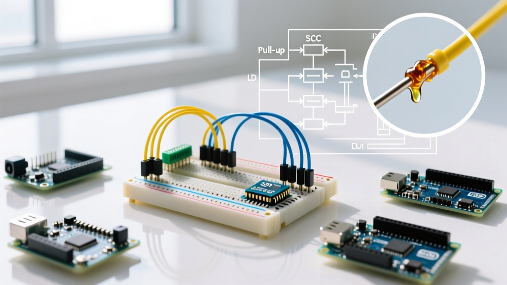
The most common cause of I2C migration failure is the blind reuse of 4.7kΩ pull-up resistors. The I2C specification dictates that the SCL and SDA lines are open-drain; they are pulled low by the devices and rely on external resistors to pull them high. The correct resistor value is entirely dependent on the bus capacitance and the desired clock speed. According to the foundational I2C specifications detailed by Analog Devices, failing to match the resistor to the capacitance will result in sluggish rise times and data corruption.
I2C Pull-Up Resistor Selection Matrix
| Bus Capacitance (pF) | Standard Mode (100 kHz) | Fast Mode (400 kHz) | Fast Mode+ (1 MHz) |
|---|---|---|---|
| < 100 pF | 10 kΩ | 4.7 kΩ | 2.2 kΩ |
| 100 pF - 200 pF | 4.7 kΩ | 2.2 kΩ | 1.0 kΩ |
| 200 pF - 400 pF | 2.2 kΩ | 1.0 kΩ | 470 Ω |
Note: The absolute maximum bus capacitance allowed by the I2C standard is 400 pF. If your wiring and device inputs exceed this, you must use bus buffers or multiplexers to segment the network.
Physical Layer Upgrades: Wiring and Trace Routing
When migrating from a breadboard prototype to a custom PCB or a permanent enclosure installation, the physical routing of your Arduino SCL SDA lines becomes critical. I2C is highly susceptible to crosstalk and electromagnetic interference (EMI).
Best Practices for 2026 Hardware Designs
- Keep Traces Short and Matched: Route SCL and SDA parallel to each other, keeping them as short as possible. Ideally, they should be routed over a solid, unbroken ground plane to provide a consistent return path and minimize loop inductance.
- Avoid High-Speed Crosstalk: Never route I2C lines parallel to high-frequency signals like SPI clocks, PWM motor control lines, or USB data pairs. If they must cross, do so at a strict 90-degree angle.
- Wire Gauge for Enclosures: If extending the I2C bus outside the PCB to a remote sensor in an enclosure, use 24 AWG to 26 AWG stranded wire. Avoid 28 AWG or thinner, as the increased resistance will degrade the voltage drop across the pull-up resistors.
- Twisted Pairs: For runs exceeding 30 cm, use twisted pair cable (like CAT5e) where SDA is twisted with Ground, and SCL is twisted with VCC. This drastically reduces common-mode noise pickup.
Step-by-Step Migration Checklist
Before powering up your newly migrated architecture, run through this hardware verification checklist to prevent silicon damage and ensure bus stability:
- Verify Logic Levels: Use a multimeter to confirm the VCC of all sensors. Ensure no 5V sensor SDA/SCL pin is directly connected to a 3.3V MCU GPIO without an active level shifter.
- Measure Idle Voltage: With the bus idle (no communication), measure the voltage on the SCL and SDA lines at the MCU pins. They should read exactly VCC (e.g., 3.28V for a 3.3V system). If they read lower, your pull-up resistors are too strong, or a device is incorrectly holding the line low.
- Scan the Bus: Upload an I2C scanner sketch. As recommended in the SparkFun I2C Tutorial, a scanner will quickly identify if devices are acknowledging their addresses or if the bus is locked up due to a missing pull-up.
- Scope the Signals: If you have access to an oscilloscope, probe the SCL line. Look for sharp, square edges. If the rising edge looks like a slow, rounded curve (an RC charging curve), your bus capacitance is too high for your current pull-up resistor value.
Troubleshooting Common Migration Failures
Even with careful planning, upgraded I2C networks can exhibit erratic behavior. Here are the most common edge cases and their solutions:
The 'Bus Lockup' Phenomenon
If your MCU resets or loses power while a sensor is actively pulling the SDA line low, the sensor will hold the line low indefinitely upon reboot, locking the bus. Solution: Implement a software bus recovery routine in your MCU's setup() function. Toggle the SCL pin as a standard GPIO output 9 times with a 5ms delay. This forces the stuck sensor to clock out its remaining bits and release the SDA line. Alternatively, use a hardware watchdog timer.
Intermittent NACK Errors
If your serial monitor occasionally shows "NACK" (Not Acknowledged) errors, especially when a relay switches or a motor starts, you are experiencing EMI-induced bit flips. Solution: Lower the I2C clock speed from 400 kHz to 100 kHz in your Wire library initialization (Wire.setClock(100000);), and add 100 nF decoupling capacitors as close to the VCC/GND pins of every I2C sensor as physically possible.
Conclusion
Migrating your Arduino SCL SDA configurations from legacy 5V paradigms to modern, high-performance 3.3V systems is a rite of passage for advanced makers. By investing in active level shifters like the PCA9306, utilizing multiplexers for complex topologies, and strictly calculating your pull-up resistors against bus capacitance, you transform I2C from a fragile hobbyist protocol into an industrial-grade communication backbone. For further reading on managing complex sensor arrays, the Adafruit TCA9548A Guide offers excellent supplementary wiring diagrams. Upgrade your hardware, respect the physics of the bus, and your projects will achieve the reliability required for real-world deployment.