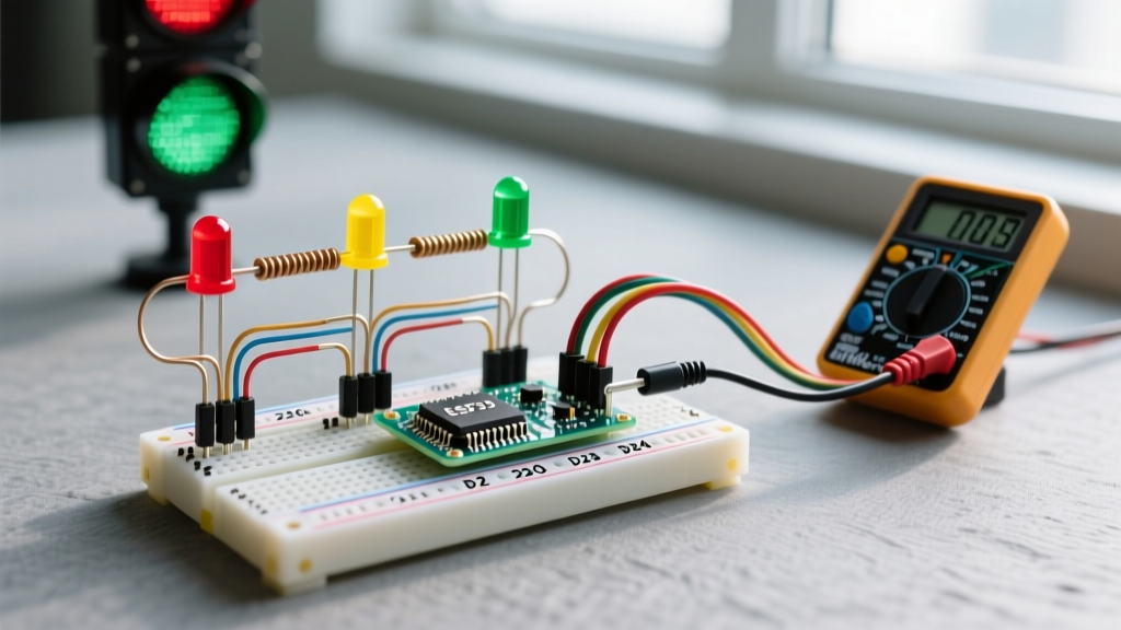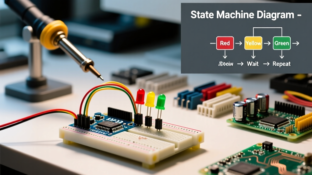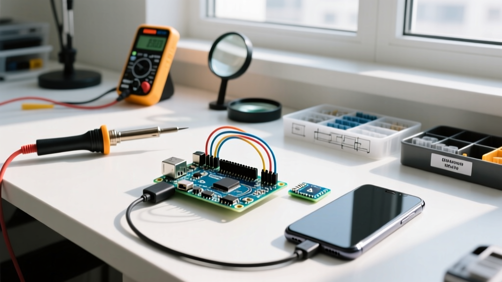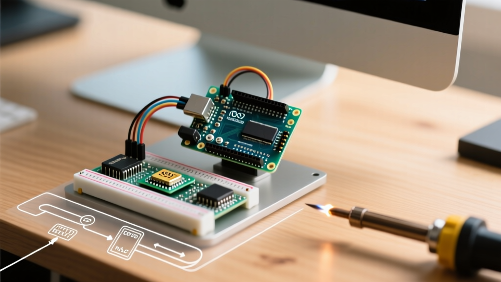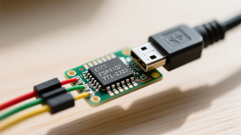

The Short Answer: Yes, But Watch Your Voltages and Pins
If you are asking, "can I program ESP32 with FTDI TTL-232R?", the short answer is yes. The FTDI TTL-232R USB-to-UART cable is a staple in the electrical engineering and maker communities for debugging and flashing firmware. However, programming a bare ESP32 module or a custom PCB with this specific cable is not as simple as plugging in a standard Arduino. You must navigate strict voltage tolerances, understand the ESP32 strapping pins, and work around the physical limitations of the FTDI cable's standard 6-pin JST connector.
Unlike dedicated ESP32 development boards (like the DevKitC or NodeMCU-32S) which feature onboard CP2102 or CH340 USB-to-serial chips with automatic reset circuitry, using the raw TTL-232R cable requires manual intervention to trigger the ESP32's serial bootloader. In this comprehensive tutorial, we will break down the exact wiring, the critical voltage warnings, and the manual boot sequence required to successfully flash your ESP32.
Identifying Your FTDI TTL-232R Cable Variant: Avoiding the 5V Trap
Before you connect a single wire, you must verify the exact part number of your FTDI cable. The TTL-232R series comes in multiple voltage variants, and choosing the wrong one will instantly destroy your microcontroller.
CRITICAL WARNING: The ESP32's I/O pins are strictly 3.3V tolerant. The absolute maximum voltage on any GPIO pin is 3.6V. Applying 5V logic to the ESP32's RX0 (GPIO3) pin will permanently fry the UART0 peripheral and potentially short the entire die.
You must use the TTL-232R-3V3 (or the TTL-232R-3V3-PCB variant). If you possess the TTL-232R-5V or TTL-232R-5V-WE, do not use it for direct ESP32 programming without a bidirectional logic level converter (like the BSS138 MOSFET circuit or a TI TXS0102).
Pinout Breakdown: TTL-232R-3V3 vs ESP32
The standard FTDI cable terminates in a 6-pin JST connector. Here is the exact mapping you need to wire the cable to a bare ESP32-WROOM-32 module or your custom PCB's programming header.
| TTL-232R-3V3 Wire Color | Signal Name | ESP32 Target Pin | Technical Notes |
|---|---|---|---|
| Black | GND | GND | Common ground is mandatory for UART reference. |
| Orange | TXD | RXD0 (GPIO3) | FTDI transmits data to the ESP32. |
| Green | RXD | TXD0 (GPIO1) | FTDI receives data from the ESP32. |
| Red | VCC (+3.3V) | 3V3 / VDD | See power limitations below. |
| Brown | RTS# | Not Connected | Used for flow control; not useful for ESP32 auto-reset. |
| Yellow | CTS# | Not Connected | Hardware flow control is disabled during flashing. |
The Power Delivery Caveat
While the red wire on the TTL-232R-3V3 outputs a regulated 3.3V, the internal traces and thin AWG wires of the USB cable are not designed to handle the current spikes of an ESP32 transmitting over WiFi. An ESP32 can draw upwards of 250mA to 300mA during RF transmission. Relying solely on the FTDI cable's VCC line can result in severe voltage droop (brownouts), causing the ESP32 to randomly reset or fail to initialize the flash memory. For reliable programming and testing, power the ESP32 from a dedicated external 3.3V LDO regulator (such as the AMS1117-3.3) and only use the FTDI cable's Black, Orange, and Green wires for data.
The Missing DTR Pin Dilemma: Why Auto-Reset Fails
If you have used standard FTDI breakout boards (like the FT232RL modules from SparkFun or Adafruit), you might be familiar with the "auto-reset" feature. These breakout boards expose both the DTR (Data Terminal Ready) and RTS (Request to Send) pins. By wiring DTR and RTS through a pair of NPN transistors (like the 2N3904) to the ESP32's EN (Reset) and GPIO0 (Boot) pins, the Arduino IDE can automatically pulse the bootloader entry sequence when you click "Upload."
However, the official FTDI TTL-232R 6-pin cable does not break out the DTR pin. The 6-pin JST connector only provides GND, CTS, VCC, TXD, RXD, and RTS. Because DTR is physically inaccessible without stripping the cable's overmold and soldering directly to Pin 2 of the internal FT232RQ chip, you cannot use the standard Espressif auto-reset circuit with an off-the-shelf TTL-232R cable.
This means you must rely on manual bootloader entry using physical pushbuttons on your custom PCB or breadboard.
Step-by-Step: Manual Bootloader Entry Wiring
To program the ESP32, the chip must be forced into the UART Serial Bootloader mode. According to the Espressif ESP32 Bootloader Documentation, this requires manipulating the strapping pins during a reset cycle.
The GPIO0 Pull-Down Requirement
On your breadboard or custom PCB, ensure you have two momentary pushbuttons wired as follows:
- RESET Button: Connects the ESP32 EN pin to GND.
- BOOT Button: Connects the ESP32 GPIO0 pin to GND.
Ensure both pins have external 10kΩ pull-up resistors tied to 3.3V so they default to a HIGH state when the buttons are released.
The "Press and Release" Flashing Dance
Because you lack the automated DTR/RTS matrix, you must manually time the bootloader entry. Follow this exact sequence when uploading code from the Arduino IDE:
- Click the Upload button in the Arduino IDE.
- Wait for the IDE to compile the sketch and display the text: "Connecting..." in the output console.
- Immediately press and hold the BOOT button (pulling GPIO0 LOW).
- While still holding BOOT, press and release the RESET button (pulsing the EN pin LOW, then letting it float HIGH).
- Release the BOOT button.
The ESP32 will now boot with GPIO0 pulled LOW, forcing it into the UART download mode. The Arduino IDE will detect the sync packet and begin flashing the firmware via the FTDI TTL-232R cable.
Configuring the Arduino IDE for FTDI Serial
To ensure the IDE communicates correctly through the FTDI Virtual COM Port (VCP) driver, configure your tools menu as follows:
- Board: ESP32 Dev Module
- Upload Speed: 115200 (Start here for reliability. You can attempt 460800 or 921600 later, but long jumper wires often cause signal degradation at higher baud rates).
- Flash Mode: QIO
- Flash Frequency: 80MHz
- Port: Select the COM port labeled "USB Serial Port" (Windows) or "/dev/tty.usbserial-XXXX" (macOS/Linux).
Note: Ensure you have installed the latest FTDI VCP drivers from the official FTDI driver page, especially if you are running Windows 11 or macOS Sonoma, where legacy drivers often fail to assign a COM port.
Troubleshooting Common FTDI-to-ESP32 Failures
When using raw UART cables, things frequently go wrong. Here is how to diagnose the most common errors.
1. "A fatal error occurred: Failed to connect to ESP32: Timed out waiting for packet header"
This is the most ubiquitous error in ESP32 development. It means the Arduino IDE is sending sync bytes, but the ESP32 is not responding.
- Swapped TX/RX: The most common mistake. Remember that the FTDI TXD (Orange) must connect to the ESP32 RXD0 (GPIO3). Serial lines must cross (TX to RX, RX to TX).
- Missed Bootloader Window: You did not execute the manual BOOT/RESET button sequence correctly, or you released the BOOT button before the IDE initiated the handshake. The ESP32 has already booted into normal application mode and is ignoring the UART flashing protocol.
- GPIO12 Strapping Conflict: If GPIO12 is pulled HIGH during boot, the ESP32 switches the flash voltage to 1.8V. If your SPI flash chip requires 3.3V, the chip will fail to initialize, and the bootloader will crash before it can even sync with the FTDI cable. Ensure GPIO12 is floating or pulled LOW.
2. "Brownout detector was triggered" in the Serial Monitor
If you successfully flash the board, but the ESP32 continuously resets when your code attempts to connect to WiFi, your power delivery is failing. As mentioned earlier, the FTDI TTL-232R's red VCC wire cannot supply the transient current required for RF calibration and WiFi transmission. Disconnect the red wire and supply the ESP32 with a robust 3.3V source capable of delivering at least 500mA.
3. Garbage Characters in the Serial Monitor
If the Serial Monitor outputs endless blocks of `@` symbols or random ASCII, your baud rate is mismatched. The ESP32 boot ROM outputs debug information at 115200 baud by default. If your Arduino IDE Serial Monitor is set to 9600, the data will appear corrupted. Additionally, if you are using excessively long jumper wires between the FTDI cable and the ESP32, signal ringing and capacitance can corrupt the UART edges. Keep TX/RX jumper wires under 15cm (6 inches) for reliable high-speed communication.
Summary: Is the TTL-232R the Right Tool?
So, can I program ESP32 with FTDI TTL-232R? Absolutely. It is an excellent, high-quality tool for debugging UART logs and flashing firmware on custom PCBs where a USB-C or Micro-USB connector was omitted to save space and BOM costs. However, the lack of a broken-out DTR pin means you must design manual BOOT and RESET buttons into your hardware. Always double-check that you are using the 3.3V variant, cross your TX and RX lines, and provide adequate external power for WiFi operations.