
Modern IDE Configuration: Moving Beyond the Basics
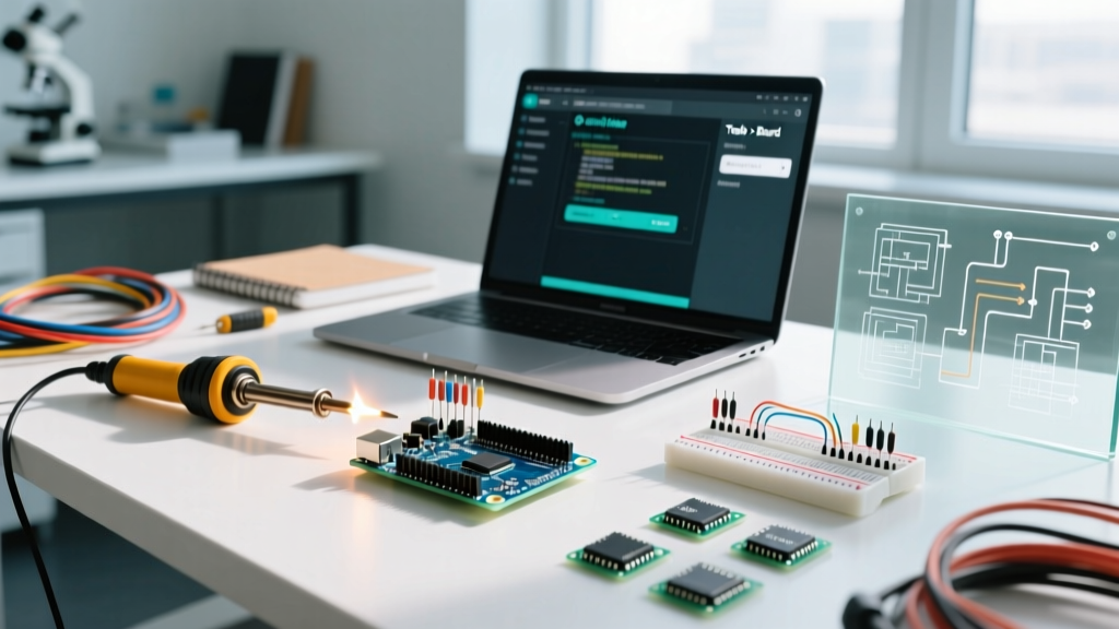
Learning how to program Arduino microcontrollers has evolved significantly. With the widespread adoption of Arduino IDE 2.x as the industry standard in 2026, the legacy 1.8.x branch is officially deprecated for new projects. The modern IDE introduces a completely revamped backend powered by the Eclipse Theia framework, offering native Apple Silicon support, real-time syntax highlighting, and an integrated serial plotter that handles high-speed data streaming without dropping frames.
However, this architectural shift means that configuring your environment to program Arduino boards—especially third-party architectures like ESP32, STM32, and the newer Renesas-based Uno R4—requires a precise understanding of the Board Manager and underlying toolchains. This guide provides a deep-dive configuration matrix and troubleshooting framework for professional makers and electronics engineers.
Deprecation Notice: Arduino IDE 1.8.19 is no longer receiving security or toolchain updates. If you are maintaining legacy CI/CD pipelines using
arduino-cli, ensure you are pulling the latest 0.35.x+ binaries to maintain compatibility with modern core packages.
Board Manager & Core Installation Matrix
Before you can program Arduino-compatible hardware, you must configure the Board Manager URLs. The default installation only includes the legacy AVR and SAMD cores. Below is the essential configuration matrix for the most widely used architectures in 2026.
| Architecture | Target Chips | Additional Board Manager URL | Current Stable Core (2026) |
|---|---|---|---|
| Espressif ESP32 | ESP32-S3, ESP32-C6 | https://raw.githubusercontent.com/espressif/arduino-esp32/gh-pages/package_esp32_index.json |
3.0.x |
| Earle Philhower RP2040 | RP2040, RP2350 | https://github.com/earlephilhower/arduino-pico/releases/download/global/package_rp2040_index.json |
4.1.x |
| STM32 Cores | STM32F103, STM32H7 | https://github.com/stm32duino/BoardManagerFiles/raw/main/package_stmicroelectronics_index.json |
2.8.x |
| ATTinyCore | ATtiny85, ATtiny1614 | http://drazzy.com/package_drazzy.com_index.json |
2.0.x |
Pro Tip: Always append these URLs in the IDE Preferences menu (File > Preferences > Additional boards manager URLs), separating multiple entries with a comma. Do not manually edit the preferences.txt file while the IDE is running, as the Theia backend will overwrite your changes upon closure.
Step-by-Step: Configuring the Arduino Uno R4 Minima
The Arduino Uno R4 series represents a massive shift from the classic ATmega328P. Priced at $19.50 for the Minima and $27.50 for the WiFi variant, these boards utilize the 32-bit Renesas RA4M1 Arm Cortex-M4 chip. Programming this board requires specific configuration steps that differ from legacy AVR boards.
- Install the Renesas Core: Open the Board Manager, search for 'Arduino Renesas Uno R4 boards', and install the latest package (approx. 45MB download).
- Configure the USB-C CDC Driver: Unlike the ATmega16U2 used on the Uno R3, the RA4M1 has native USB CDC capabilities. On Windows 11, the OS usually binds the generic
usbser.sysdriver automatically. If the port shows up as 'Unknown Device' in Device Manager, manually force-install thearduino.infdriver located in your core directory. - Adjust Upload Speed: The default upload baud rate is 115200, but the Renesas bootloader can handle higher throughput. In the IDE Tools menu, you can leave the speed on 'Auto', but if you experience timeout errors, force the upload speed to 921600 via the
boards.txtoverride. - Enable FPU (Floating Point Unit): If your sketch involves heavy trigonometric calculations or PID control loops, ensure the 'FPU' option in the Tools menu is set to 'Single Precision Hardware' to leverage the Cortex-M4 hardware math accelerator.
Troubleshooting Upload Failures & Port Configuration
When you attempt to program Arduino hardware and encounter the dreaded avrdude: stk500_recv(): programmer is not responding or bossac: No device found errors, the issue is almost always rooted in serial port handshaking or bootloader state machines.
The 1200bps Reset Trick
Modern Arduino boards (Leonardo, Micro, Nano 33 IoT, and RP2040 variants) do not have a dedicated hardware reset line tied to the DTR pin of the USB-to-Serial converter like the classic Uno. Instead, they use a software-triggered reset. When the IDE opens the serial port at exactly 1200 baud and immediately closes it, the bootloader interprets this as a command to halt the user sketch, reset the microcontroller, and enter programming mode.
Failure Mode: If your user sketch crashes immediately upon boot (e.g., a watchdog timer misconfiguration or an infinite loop in setup() that blocks USB interrupts), the board will never 'hear' the 1200bps signal.
The Fix:
- Press and hold the physical RESET button on the board.
- Click 'Upload' in the IDE.
- Watch the IDE console. The moment it says
Uploading...and shows the storage bar, release the RESET button. - This manually forces the bootloader to catch the upload handshake.
Dealing with Clone Boards and CH340G Chips
If you are programming budget-friendly clone boards (often $4 to $6 on bulk marketplaces), they likely use the WCH CH340G or CH340C USB-to-UART chip instead of the genuine FTDI FT232RL. In 2026, Windows 11 and macOS Sonoma/Sequoia include native CH340 drivers, but older OS versions require the official WCH V3.8 driver. If your COM port connects but immediately disconnects during the compile phase, it is a known DTR/RTS handshake bug in early CH340 silicon. Adding a 10µF capacitor between the RESET and GND pins can stabilize the auto-reset circuit during compilation.
Advanced Programmer Configurations (ISP & JTAG)
For production environments or when you need to burn custom bootloaders and configure hardware fuses, programming via the USB serial bootloader is insufficient. You must configure an In-System Programmer (ISP).
We highly recommend the Pololu USB AVR Programmer v2.1 (retailing at $11.95). It is fully compatible with avrdude and acts as a drop-in replacement for the discontinued AVRISP mkII.
Configuring Custom Fuses via IDE
To modify the brown-out detection (BOD) or clock source, you must edit the boards.txt file. For an ATmega328P running on an internal 8MHz oscillator (ideal for low-power battery nodes):
uno_custom.name=Custom 8MHz Internal
uno_custom.upload.maximum_size=30720
uno_custom.bootloader.low_fuses=0xE2
uno_custom.bootloader.high_fuses=0xDA
uno_custom.bootloader.extended_fuses=0xFD
After saving, restart the IDE. Select your custom board, connect the Pololu ISP to the ICSP header (ensuring the 5V line is connected if the board is unpowered), and select Tools > Burn Bootloader. This writes the fuse bytes and flashes the Optiboot hex file in a single pass.
Frequently Asked Questions (FAQ)
Can I program Arduino boards using VS Code instead of the official IDE?
Yes. The PlatformIO extension for VS Code is the preferred environment for advanced firmware engineers. It utilizes a platformio.ini configuration file, allowing you to define exact board IDs, framework versions (e.g., Arduino vs ESP-IDF), and custom build flags without relying on the IDE's GUI. However, for beginners learning how to program Arduino hardware, the official IDE 2.x provides a much gentler learning curve with its integrated Serial Monitor and board wiring diagrams.
Why does my ESP32 sketch compile but fail to upload with a 'Fatal Error: Failed to connect'?
This occurs when the ESP32's strapping pins (GPIO0, GPIO2, GPIO12, GPIO15) are pulled to incorrect logic levels by external circuitry, preventing the chip from entering UART download mode. Ensure GPIO0 is pulled LOW and GPIO2 is floating or pulled LOW during the upload sequence. Many modern ESP32 dev boards include auto-reset circuitry utilizing two NPN transistors to handle this automatically.
How do I view the exact avrdude command the IDE is executing?
Navigate to File > Preferences and check the box for Show verbose output during: upload. The black console window at the bottom of the IDE will display the full system call, including the exact path to the avrdude binary, the configuration file (avrdude.conf), and the specific memory partitions being written. This is invaluable for debugging custom memory partitioning on ATtiny and ATmega chips.
Mastering how to configure your environment to program Arduino hardware bridges the gap between simply copying sketches and engineering robust, deployable embedded systems. By understanding the underlying toolchains, bootloader state machines, and hardware interfaces, you eliminate upload friction and accelerate your prototyping workflow.