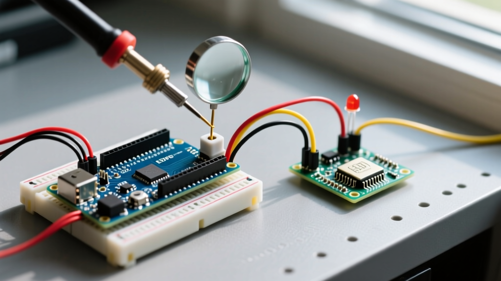

The Hidden Costs of Poorly Configured ISRs
Hardware interrupts are the backbone of responsive embedded systems, allowing your microcontroller to react to external events in microseconds without constantly polling pins. However, when an Arduino hardware interrupt fails, fires multiple times, or crashes the system, the root cause is rarely the silicon itself. In 95% of cases, the failure stems from improper pin mapping, unmanaged switch bounce, or blocking code inside the Interrupt Service Routine (ISR).
Whether you are working with a legacy ATmega328P (Arduino UNO), a modern ESP32-S3, or an RP2040-based board, debugging interrupts requires a systematic approach. This guide provides a deep-dive diagnostic framework to isolate and fix the most common hardware interrupt failures encountered in modern maker and prototyping environments.
Diagnostic Matrix: Symptom to Solution
Before diving into code, map your specific failure mode using the diagnostic matrix below. This will save hours of blind troubleshooting.
| Symptom | Probable Root Cause | Diagnostic Step | Hardware/Software Fix |
|---|---|---|---|
| ISR never triggers | Incorrect pin mapping or floating input | Verify pin supports external interrupts; check voltage with multimeter | Use digitalPinToInterrupt(); enable internal pull-ups |
| Multiple triggers per event | Mechanical switch bounce or noisy signal line | View pin signal on an oscilloscope or logic analyzer | Add RC low-pass filter or implement software timestamp guard |
| System freezes or reboots | Blocking code (e.g., delay(), Serial.print()) inside ISR |
Comment out ISR contents; use a simple flag toggle | Refactor ISR to set a volatile flag; handle logic in loop() |
| Corrupted variable values | Missing volatile keyword or non-atomic memory reads |
Check variable declarations and main loop read operations | Declare as volatile; use noInterrupts() for multi-byte reads |
1. Pin Mapping and the digitalPinToInterrupt() Trap
A frequent point of failure for beginners is assuming that the physical pin number on the silkscreen matches the interrupt vector number. According to Arduino's official attachInterrupt() documentation, passing a raw pin number to the interrupt vector argument is deprecated and will fail silently on many architectures.
Architecture-Specific Interrupt Limits
- ATmega328P (UNO/Nano): Only supports external hardware interrupts on D2 (INT0) and D3 (INT1). Attempting to attach an interrupt to D4 will compile but never fire. For other pins, you must use Pin Change Interrupts (PCINT), which require direct register manipulation.
- ESP32 / ESP32-S3: Supports GPIO interrupts on almost all pins, but RTC GPIOs (used for deep-sleep wakeups) have separate routing matrices. As noted in the Espressif ESP-IDF GPIO API reference, routing a standard ISR to an RTC-only pin during active mode can cause unpredictable behavior.
- RP2040 (Raspberry Pi Pico): Supports interrupts on all GPIOs (0-29), but GPIOs are grouped into banks. Simultaneous interrupts on the same bank require careful priority management.
Expert Fix: Always wrap your pin definition in the macro: attachInterrupt(digitalPinToInterrupt(PIN), myISR, FALLING);. This ensures the compiler translates the physical pin to the correct hardware interrupt vector regardless of the target board.
2. Ghost Triggers: Switch Bounce and Floating Pins
If your ISR fires 5 to 15 times when you press a tactile button once, you are experiencing mechanical switch bounce. When metal contacts close, they physically bounce, creating a rapid series of high/low transitions lasting between 1ms and 5ms. To a microcontroller executing instructions at 16MHz or 240MHz, this looks like a dozen distinct button presses.
Hardware Debouncing (The RC Network)
For mission-critical applications where software latency is unacceptable, implement a hardware low-pass RC filter. A standard configuration uses a 10kΩ pull-up resistor and a 100nF ceramic capacitor to ground. This creates a time constant (τ = R × C) of 1ms, effectively smoothing out the microsecond bounces before they reach the MCU pin. For harsh industrial environments, consider adding a Schmitt trigger IC (like the 74HC14) to square off the smoothed analog curve back into a crisp digital edge.
Software Debouncing (Timestamp Guard)
If you cannot modify the hardware, use a non-blocking software guard inside the ISR. Do not use delay() inside the ISR. Instead, use micros() to ignore subsequent triggers within a 2000µs window.
volatile unsigned long lastTriggerTime = 0;

void buttonISR() {
  unsigned long currentTime = micros();
  if (currentTime - lastTriggerTime > 2000) { // 2ms debounce guard
    // Valid trigger logic here
  }
  lastTriggerTime = currentTime;
}
3. The System Freeze: Blocking Code Inside the ISR
An ISR must be treated like a surgical strike: get in, change a state, and get out. When an interrupt fires, the microcontroller pauses the main program, saves the CPU state to the stack, and jumps to the ISR. If your ISR contains delay(), Serial.print(), or complex I2C/SPI transactions, you risk stack overflow, missed subsequent interrupts, or complete system lockups.
Furthermore, functions like millis() and Serial rely on their own background interrupts. If you disable global interrupts or stall the CPU inside your ISR, these background timers stop incrementing, causing millis() to freeze and serial buffers to deadlock.
The Flag-and-Poll Pattern
The industry-standard approach is to set a volatile boolean flag inside the ISR and process the heavy lifting in the main loop().
volatile bool eventFlag = false;

void fastISR() {
  eventFlag = true; // Takes less than 1µs
}

void loop() {
  if (eventFlag) {
    eventFlag = false; // Clear flag immediately
    Serial.println("Heavy processing happens here safely.");
    // Execute I2C reads, motor control, etc.
  }
}
4. Variable Corruption: volatile and Atomic Reads
A deeply misunderstood concept in Arduino programming is the volatile keyword. When the compiler optimizes your code, it may cache a variable's value in a CPU register to save memory fetch cycles. If an ISR updates that variable in the background, the main loop will never see the new value because it is reading the stale register cache. Declaring the variable as volatile forces the compiler to fetch it from SRAM every single time.
The 8-bit AVR Multi-Byte Race Condition
On 8-bit AVR boards (UNO, Mega), the CPU reads memory one byte at a time. If your ISR updates a 4-byte unsigned long (like a timestamp from micros()) at the exact moment the main loop is reading it, the main loop might read two bytes from the old value and two bytes from the new value, resulting in catastrophic data corruption.
To fix this, you must temporarily disable interrupts while reading multi-byte volatile variables in the main loop:
volatile unsigned long isrTimestamp = 0;
unsigned long safeTimestamp = 0;

void loop() {
  noInterrupts(); // Pause interrupts for atomic read
  safeTimestamp = isrTimestamp;
  interrupts();   // Resume interrupts

  // Use safeTimestamp for calculations
}
Note: On 32-bit architectures like the ESP32 or RP2040, memory reads for 32-bit integers are inherently atomic, so noInterrupts() is not strictly required for single-word variables, though it remains good practice for larger structs.
Advanced Edge Case: Interrupt Priority and Nesting
When designing complex systems with multiple sensors, you may encounter a scenario where a high-frequency sensor (like a quadrature encoder) starves a lower-priority interrupt (like a user button). On the ATmega328P, interrupt vectors have a strict hardware priority hierarchy (INT0 supersedes INT1, which supersedes Pin Change Interrupts). If INT0 is constantly firing due to noise or a high-speed signal, INT1 will never execute.
The Fix: If you are migrating to a 32-bit MCU like the ESP32 or ARM Cortex-M0+ (RP2040), utilize the Nested Vectored Interrupt Controller (NVIC). The NVIC allows you to assign explicit priority levels to different GPIO interrupts, ensuring that critical safety stops always preempt high-frequency data logging.
Summary Checklist for Bulletproof ISRs
- Verify Pin Capability: Confirm your chosen pin supports external hardware interrupts on your specific MCU.
- Use the Macro: Always use
digitalPinToInterrupt(pin). - Condition the Signal: Use pull-up resistors (internal or external 10kΩ) and hardware RC filters for mechanical switches.
- Keep it Brief: No delays, no serial prints, no blocking I/O inside the ISR.
- Declare Volatile: Any variable shared between the ISR and main loop must be
volatile. - Read Atomically: Use
noInterrupts()when reading multi-byte variables on 8-bit AVRs.
By treating hardware interrupts with the strict discipline they demand, you eliminate the erratic behaviors that plague most embedded projects. For further reading on microcontroller architecture and register-level interrupt handling, consult the Microchip ATmega328P Datasheet, specifically Section 12 on Interrupts.