
The Challenge of Generating Sound on Arduino
When makers first attempt to generate sound on Arduino boards, they quickly hit a fundamental hardware wall: microcontrollers do not natively output analog audio waveforms. A standard ATmega328P (found on the Arduino Uno) outputs strictly digital signals—either 0V or 5V. To create the complex, continuous sine and square waves required for human-audible sound (20Hz to 20kHz), we must bridge the gap between digital logic and analog acoustics.
Whether you are building a retro synthesizer, an interactive art installation, or an MP3 player, choosing the right audio generation method is critical. In this guide, we break down the three primary architectures for Arduino audio: Pulse Width Modulation (PWM), True Digital-to-Analog Converters (DAC), and dedicated I2S audio codecs. We will examine exact hardware models, circuit requirements, and the failure modes that ruin audio quality.
Method 1: PWM Audio (The 8-Bit Workhorse)
Pulse Width Modulation is the most accessible way to produce sound on 8-bit AVR boards like the Arduino Uno or Nano. By rapidly toggling a digital pin HIGH and LOW and varying the duty cycle, you can simulate an analog voltage. According to the official Arduino analog output documentation, the analogWrite() function operates at a default frequency of roughly 490Hz on most pins.
The Problem: A 490Hz switching frequency falls squarely in the middle of the human hearing range. If you connect a speaker directly to a 490Hz PWM pin, you will hear a harsh, buzzing square wave, not your intended audio sample.
The Solution: Timer Interrupts and Low-Pass Filters
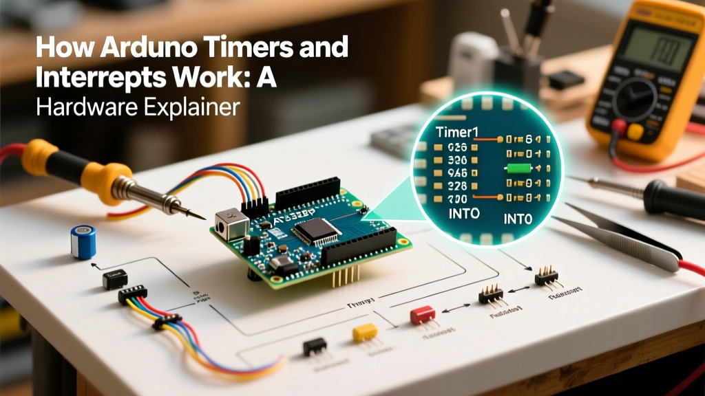
To use PWM for audio, you must reconfigure the microcontroller's hardware timers to push the PWM frequency above the audible spectrum (typically >31kHz). On the ATmega328P, modifying Timer 2 allows for a 31.25kHz PWM frequency on Pin 3 (PD3) or Pin 11 (PB3).
However, high-frequency PWM still outputs a digital square wave. You must smooth this into an analog waveform using an RC (Resistor-Capacitor) low-pass filter. A standard configuration uses a 1kΩ resistor in series with the signal, followed by a 10nF capacitor to ground. This creates a cutoff frequency of approximately 15.9kHz, effectively filtering out the 31.25kHz carrier wave while letting audio frequencies pass.
Pro-Tip: PWM audio is strictly limited to 8-bit resolution (256 voltage steps) on AVR boards. This results in a distinct "quantization noise" or hiss, making it suitable only for basic sound effects, speech synthesis, and retro 8-bit chiptunes.
Method 2: True DAC on 32-Bit ARM Architectures
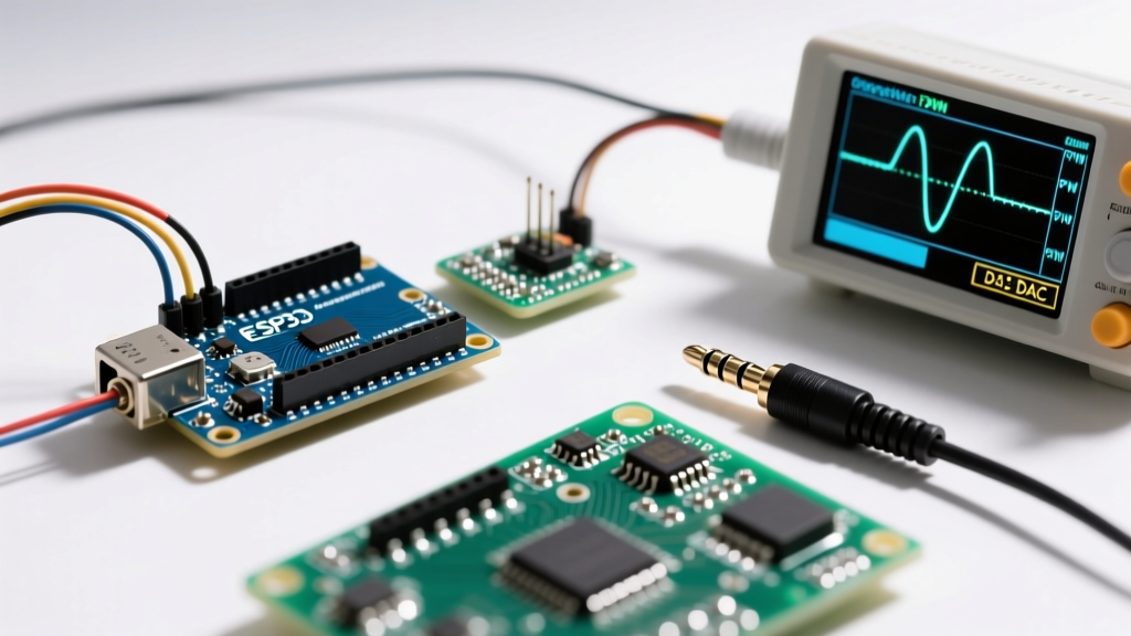
If your project requires high-fidelity waveforms, synthesizer oscillators, or clean sine waves, you need a true Digital-to-Analog Converter (DAC). Unlike PWM, a DAC outputs a genuine, continuous analog voltage without the need for aggressive low-pass filtering.
Historically, this required stepping up to the Arduino Due (SAM3X8E ARM Cortex-M3), which features dual 12-bit DAC pins (DAC0 and DAC1) capable of outputting up to 352,000 samples per second (352ksps). Today, the modern Arduino Uno R4 Minima (Renesas RA4M1 ARM Cortex-M4) also includes a native 12-bit DAC, bringing high-resolution audio to the classic Uno footprint.
Direct Digital Synthesis (DDS)
With a 12-bit DAC, you have 4,096 discrete voltage steps (compared to PWM's 256). This drastically reduces quantization noise. By using Direct Digital Synthesis (DDS) techniques, you can stream pre-calculated sine, triangle, and sawtooth wave tables from the MCU's flash memory directly to the DAC pin via DMA (Direct Memory Access). DMA is crucial here; it allows the audio buffer to stream to the DAC in the background without blocking your main loop() from reading sensors or updating displays.
Method 3: I2S and Dedicated Audio Codecs
For projects requiring polyphonic MP3 playback, WAV streaming from an SD card, or complex multi-effects processing, generating the audio signal on the MCU itself is computationally prohibitive. Instead, we offload the digital-to-analog conversion to a dedicated audio codec via the I2S (Inter-IC Sound) bus.
I2S is a serial bus standard specifically designed for digital audio. It separates the clock, word select (left/right channel), and serial data lines, ensuring pristine timing and zero jitter. For an in-depth look at high-quality I2S amplification, the Adafruit MAX98357A learning guide provides excellent wiring schemas for 32-bit boards like the ESP32 or Arduino Nano 33 IoT.
Hardware Spotlight: Audio Shields and Breakouts
- Adafruit MAX98357A I2S Amp (~$7.50): A tiny, highly efficient Class-D amplifier that takes I2S digital audio directly from the MCU and outputs up to 3.2W of analog power to a 4Ω speaker. Ideal for voice prompts and IoT alerts.
- Adafruit Music Maker Shield (VS1053 Codec) (~$29.95): Features the VLSI VS1053b DSP chip. It hardware-decodes MP3, AAC, WMA, and OGG Vorbis files directly from a microSD card, requiring only basic SPI commands from the Arduino. It also includes an 8-voice MIDI synthesizer.
- PJRC Teensy 4.1 with Audio Shield (~$85.00 combined): While technically a Teensy product, it is fully Arduino IDE compatible. As detailed in the PJRC Audio Library documentation, this setup uses a high-end SGTL5000 codec and a powerful 600MHz Cortex-M7 processor to handle real-time FFT, granular synthesis, and multi-channel mixing.
Audio Generation Methods: Comparison Matrix
Selecting the right architecture depends on your project's CPU, budget, and fidelity requirements. Use the table below to guide your hardware selection.
| Method | Resolution | CPU Overhead | Hardware Cost | Best Use Case |
|---|---|---|---|---|
| PWM (AVR 8-bit) | 8-bit (256 steps) | High (Timer Interrupts) | < $1.00 (Passive RC) | Retro chiptunes, basic alarms, speech |
| True DAC (ARM 32-bit) | 12-bit (4096 steps) | Low (via DMA) | $25 - $45 (MCU Board) | Synthesizers, function generators, clean tones |
| I2S Codec / Shield | 16 to 24-bit | Minimal (SPI/I2S transfer) | $7.50 - $35.00 | MP3 playback, complex DSP, polyphonic audio |
The Missing Link: Amplification and Impedance Matching
A catastrophic mistake beginners make when generating sound on Arduino is wiring an 8Ω speaker directly to a microcontroller GPIO pin or DAC output. Never do this.
According to Ohm's Law (I = V/R), pushing 5V through an 8Ω speaker demands 625mA of current. A standard Arduino GPIO pin is rated for an absolute maximum of 20mA to 40mA. Connecting a speaker directly will instantly overheat and permanently destroy the microcontroller's silicon die.
Proper Amplification Stages
DAC and PWM outputs are line-level signals. They possess the correct voltage waveform but lack the current capacity to move the physical cone of a speaker. You must introduce an amplifier stage:
- Op-Amp Buffer (LM386): The classic LM386N-1 IC costs about $1.50 and can safely drive small 8Ω speakers up to 0.5W. It requires minimal external capacitors but introduces noticeable crossover distortion.
- Class-D Amplifier (PAM8403 / MAX98357A): Class-D amps use high-frequency PWM internally to amplify the signal with >90% efficiency. The PAM8403 is a stereo 3W amp available on breakout boards for roughly $2.00. It runs cool, requires no heatsink, and operates perfectly off the Arduino's 5V rail.
Troubleshooting Common Audio Artifacts
Even with the correct hardware, audio projects are plagued by signal integrity issues. Here is how to diagnose and fix the three most common failure modes.
1. Aliasing and "Metallic" Ringing
Cause: Violating the Nyquist-Shannon sampling theorem. If your audio sample rate is 16kHz, the highest frequency you can reproduce is 8kHz. Any frequencies above 8kHz in your source file will "fold back" into the audible spectrum as harsh, metallic ringing.
Fix: Ensure your source WAV files are low-pass filtered on your PC before transferring them to the SD card. Alternatively, increase your MCU sample rate to at least 22.05kHz or 44.1kHz (CD quality).
2. 50/60Hz Ground Loop Hum
Cause: When the Arduino, the audio amplifier, and the power supply share a common ground wire that is too thin or daisy-chained, the high-current spikes from the speaker travel back through the ground line, modulating the MCU's reference voltage.
Fix: Implement Star Grounding. Run separate, thick ground wires from the power supply's ground terminal directly to the Arduino GND and the Amplifier GND. Do not daisy-chain grounds through the breadboard. For extreme cases, use an audio isolation transformer between the DAC and the amplifier.
3. Clipping and Square-Wave Distortion
Cause: Sending an audio signal that exceeds the amplifier's input voltage range. If your DAC outputs a 3.3V peak-to-peak sine wave, but your amplifier's input stage expects a 1V line-level signal, the peaks will be chopped off (clipped), turning your sine wave into a square wave and generating harsh harmonics.
Fix: Insert a voltage divider or a 10kΩ/10kΩ potentiometer between the audio source and the amplifier input to attenuate the signal to the correct line level.
Summary
Mastering sound on Arduino requires moving beyond simple tone() commands. By understanding the physical limitations of PWM, leveraging the precision of ARM-based DACs, and utilizing I2S codecs for heavy DSP lifting, you can achieve studio-quality audio in your embedded projects. Always respect impedance matching, isolate your analog grounds from digital noise, and choose your sample rates wisely to ensure crisp, artifact-free playback.