
The Case for Upgrading Your Legacy pH Sensor
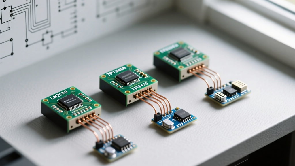
If you have been working with water quality monitoring for more than a few months, you are likely familiar with the classic generic analog pH sensor. Often bundled with a BNC connector and a tiny blue potentiometer on an LM393 op-amp board, these $15 modules are the default starting point for almost every pH meter Arduino tutorial on the web. While they are excellent for learning basic ADC (Analog-to-Digital Converter) principles, they are notoriously inadequate for real-world deployment in hydroponics, aquaculture, or automated brewing.
Legacy analog boards suffer from three critical failure modes: severe susceptibility to electromagnetic interference (EMI), lack of onboard temperature compensation, and rapid reference junction drift. As of 2026, the maker ecosystem has matured, offering robust, lab-grade digital alternatives that integrate seamlessly with modern microcontrollers like the ESP32, Arduino Uno R4, and Teensy 4.1. This migration guide will walk you through upgrading your hardware, rewriting your firmware, and implementing professional calibration protocols.
Migration Matrix: Legacy V1 vs. DFRobot V2 vs. Atlas EZO
Before ripping out your existing wiring, it is crucial to select the right upgrade path based on your precision requirements and budget. Below is a technical comparison of the three most common architectures.
| Feature | Generic Analog V1 (Legacy) | DFRobot Gravity V2 (SEN0169) | Atlas Scientific EZO-PHP-LV |
|---|---|---|---|
| Typical Cost (2026) | $12 - $18 | $35 - $45 | $115 - $140 |
| Interface | Analog (0-5V) | I2C / UART (Gravity Connector) | I2C / UART (Selectable) |
| ADC Resolution | 10-bit (MCU dependent) | 16-bit (Onboard MCU) | 16-bit (Onboard MCU) |
| Temp Compensation | None (Manual math required) | Software-based via I2C | Hardware/Software via PT1000 |
| Accuracy | ± 0.2 pH | ± 0.1 pH | ± 0.002 pH |
| Ground Isolation | None | None (Requires external isolation) | Opto-isolated I2C/UART |
Hardware Migration Path 1: The Mid-Tier DFRobot V2
The DFRobot Gravity: Analog pH Sensor V2 (SKU: SEN0169) is the most logical step up for hobbyists and intermediate makers. Unlike the legacy version, the V2 board features an onboard microcontroller that handles the ADC sampling, noise filtering, and I2C communication. This completely bypasses the noisy analog readings caused by the Arduino's internal switching regulators.
Wiring and Ground Loop Mitigation
When migrating from analog to I2C, your physical wiring changes significantly. You will move from the A0 pin to the SDA and SCL lines. However, the most common edge case during this migration is the introduction of ground loops. If your Arduino shares a common ground with water pumps, solenoid valves, or relay modules, the switching noise will travel through the ground plane and corrupt the pH probe's millivolt signal.
Pro Tip: If you observe erratic pH jumps every time a peristaltic pump turns on, you have a ground loop. Solve this by powering the pH sensor circuit through an isolated DC-DC converter, such as a B0505S (5V to 5V isolated), and use an I2C isolator chip like the ISO1540 to break the ground connection between the sensor and the main microcontroller.
Hardware Migration Path 2: Lab-Grade Atlas Scientific EZO
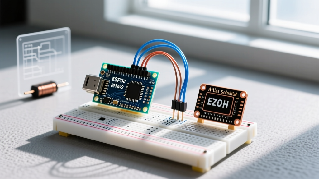
For commercial deployments, university research, or high-stakes aquaculture, the Atlas Scientific EZO-PHP-LV circuit paired with an E-201-C-03 lab-grade probe is the industry standard. According to Atlas Scientific's technical documentation, the EZO circuit embeds a highly calibrated microcontroller that stores the calibration data directly on the chip, meaning if your main Arduino crashes or is replaced, the probe retains its calibration.
Protocol Toggling: UART vs. I2C
Out of the box, the Atlas EZO circuit operates in UART mode at 9600 baud. To migrate an I2C-based Arduino architecture, you must send a one-time command to switch protocols. By connecting the TX/RX pins to a hardware serial port and sending the string I2C,102\r, the device permanently shifts to I2C mode at the default hex address 0x65. This persistence across power cycles is a massive advantage over legacy setups that require recalibration upon every reboot.
Software Migration and the Nernst Equation
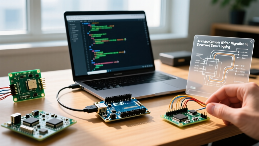
Migrating your codebase requires moving away from simple analogRead() mapping. In the legacy setup, a reading of ~512 on a 10-bit ADC roughly equated to pH 7.00. In modern digital setups, you will use the Arduino Wire library to request byte arrays containing floating-point strings.
Implementing Automatic Temperature Compensation (ATC)
The most critical software upgrade is implementing ATC. pH is not a static measurement; it is fundamentally tied to the temperature of the solution. As detailed by the USGS Water Science School, the activity of hydrogen ions changes with thermal energy. The Nernst equation dictates that the pH reading shifts by approximately -0.003 pH units per °C deviation from the calibration temperature (usually 25°C) for solutions above pH 7.0.
If you calibrate your probe at 20°C and measure a hydroponic reservoir at 30°C without ATC, your reading will be skewed by nearly 0.1 pH—a massive error that could trigger incorrect dosing pumps. Modern setups require you to pass the current temperature (read via a waterproof DS18B20 or PT1000 sensor) into the pH library's compensation function before finalizing the reading.
The Professional Calibration Protocol
Upgrading your hardware is useless if your calibration methodology remains amateur. Discard the single-point calibration method. For any serious application, a 2-point or 3-point calibration is mandatory to establish the correct slope and offset for the probe's aging glass membrane.
- Preparation: Prepare fresh pH 4.01, 7.00, and 10.01 buffer solutions. Do not reuse buffers.
- Cleaning: Rinse the probe with deionized (DI) water. Never use tap water, as the dissolved minerals will contaminate the reference junction.
- Drying: Gently dab the probe with a lint-free laboratory wipe (e.g., Kimwipes). Never rub the glass bulb, as this generates static electricity that causes reading drift.
- Thermal Equilibrium: Submerge the probe in the pH 7.00 buffer and wait a full 60 seconds. The temperature of the glass bulb must match the buffer exactly.
- Mid-Point Calibration: Send the calibration command via I2C/UART (e.g.,
Cal,mid,7.00for Atlas). - Slope Calibration: Rinse, dry, and repeat the process for pH 4.01 (low slope) and pH 10.01 (high slope).
Troubleshooting Edge Cases and Probe Maintenance
Even with a $140 Atlas EZO setup, you will encounter edge cases if maintenance is neglected. The most frequent support issue in automated pH systems is reference junction clogging.
Diagnosing a Clogged Junction
The reference junction is the porous ceramic frit that allows the internal KCl (Potassium Chloride) electrolyte to slowly leak into the sample, completing the electrical circuit. If you measure highly turbid water, nutrient-dense hydroponic solutions, or water with heavy metal particulates, this frit will clog. Symptoms include extremely slow response times (taking 5+ minutes to stabilize) and a failure to read below pH 5.0 or above pH 9.0.
The Revival Procedure
If your probe exhibits these symptoms, do not throw it away. Perform the following revival protocol:
- Soak the probe tip in a solution of 0.1M HCl (Hydrochloric Acid) for 15 minutes to dissolve mineral scaling.
- Rinse thoroughly with DI water.
- Soak the probe in warm (50°C) 3M KCl storage solution for 2 hours to rehydrate the ceramic frit and replenish the internal electrolyte.
Critical Storage Warning: Never store your pH probe in DI or distilled water. The osmotic pressure will cause the internal ions to leach out of the glass membrane and reference electrolyte, permanently degrading the probe's lifespan. Always store in 3M KCl solution.
Conclusion: The ROI of Migration
Migrating your pH meter Arduino project from a legacy analog board to a digital I2C architecture like the DFRobot V2 or Atlas EZO requires an upfront investment of both capital and development time. However, the return on investment is realized through the elimination of phantom dosing events, the reduction of manual recalibration labor, and the ability to deploy your system in electrically noisy, real-world environments. By implementing proper ground isolation, ATC, and rigorous buffer protocols, your microcontroller transitions from a fragile science experiment into a reliable, industrial-grade water quality monitor.