
The Hardware Layer: Standard and High-Power LED Wiring
Configuring an Arduino LED circuit goes far beyond the basic digitalWrite(13, HIGH) blink sketch. Whether you are driving a single 5mm indicator or a 5-meter strip of addressable RGBs, proper hardware configuration dictates the lifespan of both your light-emitting diodes and your microcontroller. In 2026, with the proliferation of low-voltage MCUs like the RP2040 and ESP32 alongside the classic ATmega328P, understanding voltage thresholds and current limits is critical.
Current Limiting and Resistor Selection
The ATmega328P (found in the Arduino Uno and Nano) has an absolute maximum current rating of 40mA per I/O pin, but the recommended continuous operating current is 20mA. Exceeding this degrades the silicon and causes voltage sag. To configure a standard LED, you must calculate the current-limiting resistor using Ohm's Law: R = (Vcc - Vf) / If.
| LED Color | Typical Forward Voltage (Vf) | Target Current (If) | Calculated Resistor (5V Vcc) | Standard E12 Value |
|---|---|---|---|---|
| Red | 2.0V | 20mA | 150Ω | 150Ω |
| Green | 2.2V | 20mA | 140Ω | 150Ω |
| Blue / White | 3.2V | 20mA | 90Ω | 91Ω |
| IR (Infrared) | 1.2V | 20mA | 190Ω | 180Ω or 200Ω |
Scaling Up: Driving 1W and 3W Star LEDs
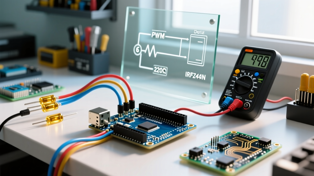
High-power LEDs, such as the Cree XPE or generic 1W/3W aluminum star PCBs, require 350mA to 700mA. You cannot drive these directly from an Arduino GPIO pin. The correct configuration uses a logic-level N-Channel MOSFET, such as the IRLZ44N (typically $1.20 - $1.50 per unit). The IRLZ44N has a low Gate-Source threshold voltage (Vgs(th) max 2.0V), meaning it fully opens with the 5V logic of a standard Arduino.
- Gate: Connect to the Arduino PWM pin via a 100Ω gate resistor (prevents high-frequency ringing).
- Pull-down: Add a 10kΩ resistor between Gate and Source to ensure the MOSFET stays off during MCU boot-up when pins are floating.
- Source: Connect to system Ground.
- Drain: Connect to the Cathode (negative) of the LED.
Expert Thermal Note: Even though the IRLZ44N has a low Rds(on), driving a 3W LED at 700mA will generate heat. Always mount the MOSFET to a small TO-220 heatsink if the ambient temperature exceeds 35°C or if the PWM duty cycle remains above 80% for extended periods.
The Software Layer: Optimizing PWM Frequencies
Pulse Width Modulation (PWM) is how we simulate analog dimming on digital pins. However, the default Arduino analogWrite() Reference configures timers to output at roughly 490Hz or 980Hz. While fine for basic visual dimming, these low frequencies cause severe "banding" or flickering when recorded on modern smartphone cameras or high-speed industrial sensors.
Reconfiguring Timer1 for Flicker-Free Dimming
To achieve a camera-friendly 20kHz+ PWM frequency on an Arduino Uno (ATmega328P), you must reconfigure the hardware timers directly in your setup() function. Pins 9 and 10 are controlled by Timer1.
// Set Timer1 to Fast PWM, 8-bit resolution, no prescaler
// This yields ~31.3kHz on a 16MHz Uno
void setup() {
  pinMode(9, OUTPUT);
  pinMode(10, OUTPUT);
  TCCR1A = _BV(COM1A1) | _BV(COM1B1) | _BV(WGM10);
  TCCR1B = _BV(WGM12) | _BV(CS10);
}

void loop() {
  // Use standard analogWrite, but it now runs at 31.3kHz
  analogWrite(9, 128); // 50% duty cycle
  delay(1000);
}
Warning: Altering Timer1 will break the standard Servo.h library, which relies on the default Timer1 configuration. If you need both high-frequency PWM and servos, use Timer2 (Pins 3 and 11) or migrate to an Arduino Nano Every, which features independent timers for every pin.
Addressable RGB Configuration (WS2812B / NeoPixel)
The WS2812B (often branded as NeoPixel) remains the industry standard for addressable Arduino LED projects. However, misconfiguration leads to erratic color shifting, dead pixels, and brownout resets. Follow this strict configuration protocol for 2026 builds.
Hardware Wiring Rules
- Bulk Capacitance: Place a 1000µF, 6.3V (or higher) electrolytic capacitor across the 5V and GND rails before the strip. This absorbs the initial current spike when all LEDs turn white simultaneously, preventing MCU brownouts.
- Data Line Resistor: Insert a 300Ω to 500Ω resistor on the data line, as close to the first LED's DIN pad as possible. This protects the internal logic IC from voltage spikes.
- The 3.3V Logic Trap: Modern boards like the ESP32, Raspberry Pi Pico (RP2040), and Arduino Nano 33 IoT output 3.3V logic. The WS2812B datasheet specifies a minimum HIGH signal of ~3.5V (0.7 x Vcc). While some modern WS2812B-V5 variants tolerate 3.3V, it is highly unreliable over long runs. Fix: Use a 74AHCT125 or SN74LVC1T45 logic level shifter ($0.85) to boost the 3.3V data signal to 5V.
Power Injection Matrix
Copper traces on standard 5M WS2812B strips (usually 2oz copper) suffer from severe voltage drop. A white pixel draws ~60mA. A strip of 60 LEDs draws 3.6A, causing the far end to drop below 3.5V and turn pink/orange.
| LED Density (per meter) | Max Run on Single Injection | Injection Strategy |
|---|---|---|
| 30 LEDs/m (150 total) | ~2.5 meters | Inject 5V/GND at the start and midpoint. |
| 60 LEDs/m (300 total) | ~1 meter | Inject 5V/GND every 1 meter. Use 18 AWG wire. |
| 144 LEDs/m (720 total) | ~0.5 meters | Inject 5V/GND every 0.5 meters. Use 16 AWG wire. |
Library Configuration: FastLED vs. Adafruit NeoPixel
When writing the firmware, your library choice impacts RAM usage and rendering speed. According to the Adafruit NeoPixel Überguide, the official library is beginner-friendly but halts all interrupts during the data transmission phase, which can disrupt Wi-Fi on ESP32s or IR remote reading.
For advanced configurations, FastLED is the superior choice. It utilizes hardware SPI or I2S (on ESP32) to push data without blocking interrupts. To configure FastLED for a WS2812B strip on Pin 6 with 60 LEDs, your initialization looks like this:
#define DATA_PIN 6
#define NUM_LEDS 60
CRGB leds[NUM_LEDS];

void setup() {
  // FastLED automatically handles the 3.5V timing requirements
  FastLED.addLeds<WS2812B, DATA_PIN, GRB>(leds, NUM_LEDS);
  FastLED.setBrightness(128); // Hard cap to prevent power supply overload
}
Troubleshooting Matrix: Common Arduino LED Failures
| Symptom | Root Cause | Configuration Fix |
|---|---|---|
| First pixel is always yellow/green, rest are correct. | Missing common ground reference between MCU and LED strip power supply. | Connect MCU GND directly to the LED power supply GND. |
| Random flickering or "noise" on the strip. | Data line is too long, or lacks a terminating resistor. | Add 330Ω resistor on DIN. Keep data wire under 50cm. Add a "null pixel" as a signal repeater if longer. |
| MCU resets when LEDs turn bright white. | Voltage sag on the 5V rail triggering the MCU's brownout detection (BOD). | Install 1000µF bulk capacitor. Power MCU and LEDs from separate buck converters tied at GND. |
| Colors are swapped (e.g., code says Red, strip shows Blue). | Incorrect color order definition in software. | Change FastLED definition from GRB to RGB or BRG depending on the specific LED batch. |
By treating your Arduino LED project as a complete system—balancing electrical limits, signal integrity, and software timing—you eliminate the guesswork and build installations that run reliably for years.