
The Hidden Culprit Behind 90% of Arduino Debugging Nightmares
If you have ever spent three hours debugging an I2C sensor on your Arduino Uno, only to realize the SDA line was floating because of a loose wire, you have experienced the "Dupont tax." When integrating a Dupont jumper cable into an Arduino circuit, the physical connection is just as critical as the logic in your sketch. The term "Dupont" is actually a genericized trademark originating from the EDAC 5100 series connectors, which established the ubiquitous 2.54mm (0.1 inch) pitch standard we rely on for breadboards and pin headers today.
While pre-made jumper wires are convenient, they are often the weakest link in prototyping. Cheap, mass-produced cables suffer from high contact resistance, brittle PVC insulation, and poorly crimped terminals that back out of their nylon housings. In this comprehensive 2026 guide, we will walk through exactly how to select, crimp, and troubleshoot custom Dupont jumper cables for Arduino projects, ensuring your hardware connections are as reliable as your code.
Anatomy of a Dupont Jumper Cable for Arduino Setups
Before stripping a single wire, you must understand the mechanical and electrical tolerances of the 2.54mm pitch ecosystem. A standard Dupont jumper consists of three components: the terminal (male or female), the housing (typically PBT or Nylon), and the wire.
Wire Gauge and Stranding Specifications
Most generic pre-made jumpers use 28 AWG (American Wire Gauge) stranded copper. However, the stranding count and insulation material drastically affect flexibility and durability. For premium Arduino prototyping, upgrading to silicone-insulated wire is highly recommended. Silicone withstands temperatures up to 200°C (meaning it won't melt if you accidentally touch it with a soldering iron) and offers superior flexibility.
| Wire Gauge | Typical Stranding | Max Current (Breadboard) | Resistance per Meter | Best Use Case |
|---|---|---|---|---|
| 28 AWG (Standard) | 7/36 (7 strands) | 1.5 Amps | ~0.213 Ω | Logic signals, I2C, SPI, UART |
| 26 AWG (Heavy) | 19/38 (19 strands) | 2.5 Amps | ~0.134 Ω | 5V/3.3V power rails, small servos |
| 24 AWG (Power) | 40/40 (40 strands) | 3.5 Amps | ~0.084 Ω | High-current motors, LED strips |
Note: Breadboard leaf-springs are the actual bottleneck for current. Never push more than 2 Amps through a standard solderless breadboard, regardless of your wire gauge.
Step-by-Step: How to Crimp Your Own Dupont Jumper Cables
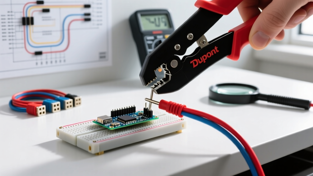
Building your own custom-length jumpers eliminates the messy "spaghetti wire" look on your breadboard and ensures a high-quality gas-tight crimp. To achieve professional results, you need the right tooling. The IWISS SN-28B or the Japanese-engineered Engineer PA-09 ratchet crimpers (typically priced between $18 and $35) are the gold standards for hobbyists in 2026. Avoid the cheap, non-ratcheting stamping tools included in generic kits; they deform the terminal wings and cause intermittent connections.
Pro-Tip: Always buy terminals with "gold flash" plating rather than tin. Gold prevents oxidation in low-voltage (3.3V) Arduino logic circuits, ensuring reliable signal transmission over time.
The 4-Step Crimping Process
- Strip the Wire Precisely: Use a precision wire stripper (like the WS-04B) to remove exactly 3.0mm of insulation. If you strip too much, bare copper will sit under the conductor wings, leading to metal fatigue and snapping. If you strip too little, the insulation wings will crush the bare copper, causing a short circuit risk.
- Crimp the Conductor Wings: Place the terminal in the ratchet crimper's "1.9" or "1.4" jaw (depending on your AWG). Insert the stripped wire so the bare copper is perfectly centered in the smaller front wings. Squeeze the ratchet until it releases. This forms the electrical gas-tight seal.
- Crimp the Insulation Wings: The larger rear wings should simultaneously fold over the PVC or silicone insulation. This provides strain relief. If using silicone wire, you may need to slightly tighten the crimper's adjustment dial, as silicone is thicker and more compressible than PVC.
- The Tug Test and Housing Insertion: Give the wire a firm tug. A proper crimp will hold over 15 lbs of pull force. Finally, slide the terminal into the PBT housing until you hear a distinct "click," indicating the terminal's barb has locked into the plastic housing.
For deeper visual references on terminal deformation and jaw alignment, consult the Adafruit Crimping Wires and Connectors guide, which remains an industry-standard visual reference for makers.
Troubleshooting Intermittent Dupont Jumper Cable Arduino Failures
Even with perfect crimps, Dupont connections can fail due to environmental and mechanical factors. Here is how to diagnose and fix the most common edge cases encountered in the field.
1. Breadboard Leaf-Spring Fatigue
Standard solderless breadboards use tiny metal leaf-springs to grip the jumper pins. In low-cost breadboards, these springs are often made from tin-plated steel rather than beryllium copper. After 3 to 4 insertions of a thick male Dupont pin, the steel permanently deforms. Symptom: The Arduino serial monitor shows random noise, or I2C devices randomly drop off the bus. Fix: Rotate your jumper wires to unused breadboard rows, or invest in premium breadboards like the BB400 from Bus Pirate or SparkFun, which use high-grade phosphor bronze contacts.
2. Voltage Drop on Power Rails
When powering an Arduino Nano via the 5V pin through a 20cm generic 28 AWG jumper, you are introducing resistance into your power delivery. If you attach a servo motor that draws 800mA during stall, Ohm's Law dictates a significant voltage drop across the wire and the breadboard traces. Symptom: The Arduino resets randomly when the servo moves. Fix: Use 24 AWG or 22 AWG silicone wire for power and ground lines, bypassing the breadboard entirely for high-current paths.
3. Terminal Back-Out
If a female Dupont connector feels loose when pushed onto an Arduino header pin, the internal metal terminal is likely lacking proper spring tension, or the plastic housing barb is broken. Fix: Use a sewing needle to lift the small metal tang on the terminal, increasing its grip on the male header pin. For a detailed breakdown of wire stranding and mechanical stress, review SparkFun's Working with Wire tutorial.
Pre-Made vs. DIY: Cost and Reliability Matrix
Is it worth crimping your own Dupont jumper cables for Arduino projects? The answer depends on your prototyping volume and quality requirements.
| Category | Generic Pre-Made (AliExpress/Amazon) | Premium Pre-Made (Adafruit/SparkFun) | DIY Custom Crimped |
|---|---|---|---|
| Cost per Wire | $0.02 - $0.05 | $0.30 - $0.45 | $0.08 - $0.12 |
| Insulation | Brittle PVC | Silicone / High-Flex PVC | Your Choice (Silicone recommended) |
| Length Options | Fixed (10cm, 20cm, 30cm) | Fixed (Usually 15cm) | Infinite (Custom to exact millimeter) |
| Crimp Reliability | Low (Machine stamped, high failure rate) | High (Factory QA tested) | Very High (Ratchet crimped, gas-tight) |
Best Practices for 2026 Arduino Prototyping
While the 2.54mm Dupont standard remains the undisputed king of the solderless breadboard, the maker ecosystem in 2026 is increasingly shifting toward more secure locking connectors for "semi-permanent" prototypes. If your Arduino project is graduating from the breadboard to a project box, consider transitioning to JST-SH (1.0mm pitch) or Molex PicoBlade (1.25mm pitch) connectors. These feature positive locking tabs that vibrate-proof your connections, a critical requirement for robotics, drones, and automotive Arduino applications.
However, for daily bench work, sensor testing, and rapid iteration, mastering the art of the custom Dupont jumper cable remains an essential skill. By investing in a quality ratchet crimper, sourcing 28 AWG silicone wire, and respecting the mechanical limits of your breadboard, you will eliminate hardware-level bugs and spend your time where it belongs: writing great firmware.
Further Reading on Connector Standards
For those interested in the historical and mechanical engineering behind the 2.54mm pitch standard that governs Arduino headers, the Wikipedia entry on Pin Headers provides excellent context on how these physical interfaces evolved to become the universal language of microcontroller prototyping.