
Beyond analogRead(): The Reality of Potentiometer Value Arduino Configurations
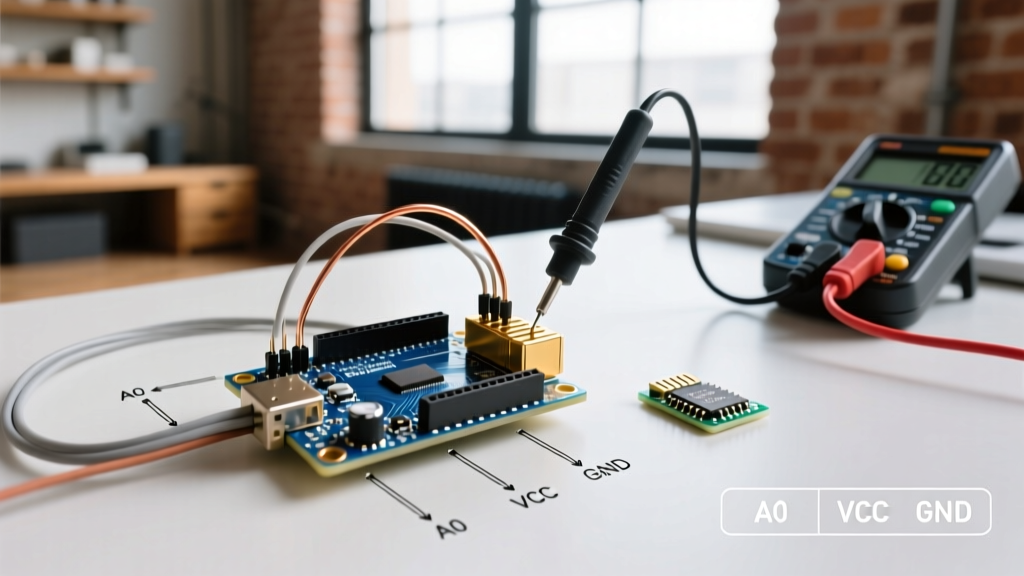
Reading a potentiometer value Arduino setup is often the first analog exercise a maker tackles. You wire the wiper to A0, call analogRead(), and watch the serial monitor. However, transitioning from a blinking LED prototype to a reliable 2026 production instrument requires a deep understanding of Analog-to-Digital Converter (ADC) architecture, impedance matching, and digital signal processing. A raw potentiometer reading is rarely clean; it is plagued by thermal noise, wiper contact bounce, and electromagnetic interference (EMI). This configuration guide details how to engineer a robust, jitter-free analog input pipeline for modern microcontrollers.
Hardware Selection: Choosing the Right Resistive Element
Not all potentiometers are created equal. The resistive track material dictates the rotational smoothness, lifespan, and inherent electrical noise (wiper noise) of your sensor. When configuring your hardware, select the component based on your application's precision requirements.
| Track Material | Example Model (2026 Pricing) | Resolution & Noise | Best Use Case |
|---|---|---|---|
| Carbon Composition | Alps RK09K1130A0R (~$0.85) | Low cost, high wiper noise, 15k cycle life | Audio volume, non-critical UI knobs |
| Cermet (Ceramic/Metal) | Bourns 3386P-1-103LF (~$1.45) | High stability, low tempco (100ppm/°C), 200 cycle life | Trimpots, calibration dials, one-time setup |
| Conductive Plastic | Vishay P16SP103K (~$5.20) | Virtually zero wiper noise, infinite resolution, 5M cycle life | Industrial joysticks, precision servo control |
Before writing a single line of smoothing code, implement a hardware RC filter. By placing a 100nF (0.1µF) ceramic capacitor between the ADC input pin and ground, you create a first-order low-pass filter with the 10kΩ potentiometer. The cutoff frequency ($f_c$) is calculated as $1 / (2 \pi R C)$. With a 10kΩ pot and 100nF cap, $f_c \approx 159Hz$. This physically blocks high-frequency EMI and wiper bounce from ever reaching the MCU's sample-and-hold capacitor.
MCU-Specific ADC Configuration Strategies
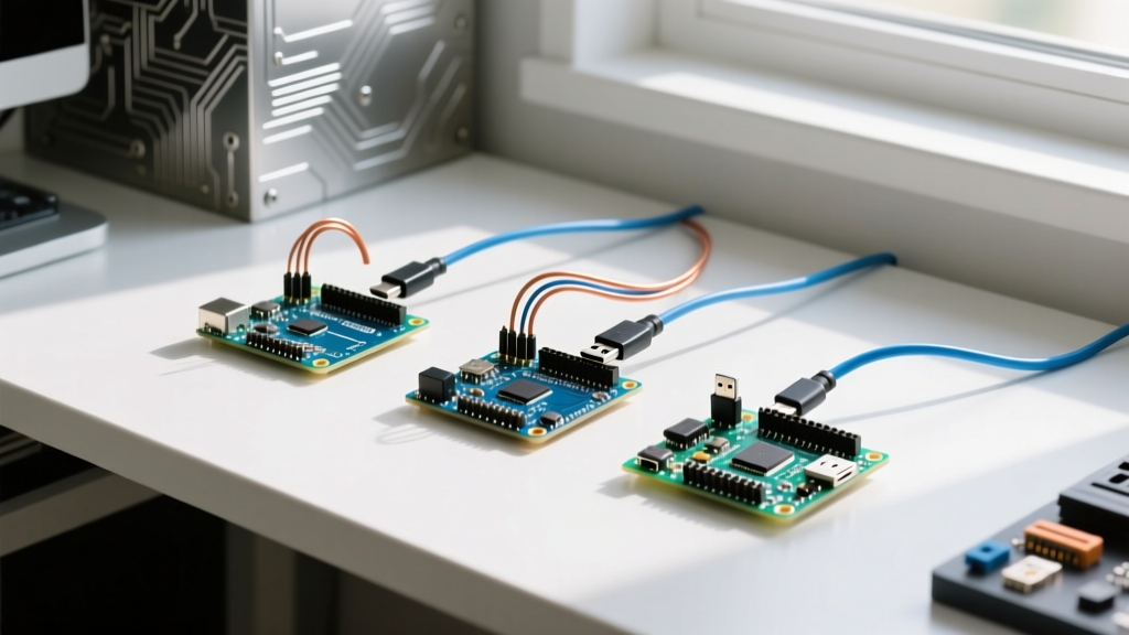
The method for extracting an accurate potentiometervalue varies drastically depending on the silicon architecture of your board. According to the official Arduino analogRead reference, the default behavior abstracts away critical hardware registers, which can lead to suboptimal sampling.
1. Classic AVR (ATmega328P / Arduino Uno R3)
The ATmega328P features a 10-bit Successive Approximation Register (SAR) ADC. For maximum accuracy, the ADC clock must be configured between 50kHz and 200kHz. The Arduino core defaults to a prescaler of 128, yielding a 125kHz ADC clock (assuming a 16MHz system clock), which is optimal. However, if you are reading multiple analog pins, you must account for the internal sample-and-hold (S/H) capacitor. If the source impedance (your potentiometer) exceeds 10kΩ, the S/H capacitor may not fully charge during the sampling window, resulting in 'ghosting' from the previously read pin.
2. Modern Renesas (Arduino Uno R4 Minima)
The Uno R4 Minima utilizes the Renesas RA4M1, featuring a 14-bit ADC. To leverage this resolution in 2026, you must configure the hardware oversampling registers. By enabling 4x or 16x hardware averaging in the ADC14 registers, you can achieve a true 14-bit output without taxing the CPU, vastly improving the signal-to-noise ratio (SNR) for precision instrument calibration.
3. Espressif ESP32-S3
The ESP32-S3 uses a 12-bit SAR ADC, but it is notoriously non-linear at the voltage rails (near 0V and 3.3V). When configuring the ESP32, you must set the correct attenuation. As detailed in the Espressif ESP-IDF ADC Oneshot Driver documentation, using ADC_ATTEN_DB_11 allows a full-scale voltage of ~3.1V. To avoid the non-linear dead zones, design your voltage divider to keep the potentiometer wiper output strictly between 0.15V and 2.9V.
Software Calibration and Digital Filtering
Even with a hardware RC filter, quantization noise and minor mechanical vibrations will cause the least significant bits (LSBs) to flutter. A simple Moving Average (SMA) requires storing an array of past values, consuming precious SRAM on 8-bit AVRs. Instead, use an Exponential Moving Average (EMA) filter.
The EMA Algorithm Implementation
The EMA filter applies a weighting factor ($\alpha$) to the newest reading while retaining a fraction of the historical reading. It requires only one variable to store the historical state.
// EMA Filter Configuration for Potentiometer Value Arduino
const float alpha = 0.15; // Smoothing factor (lower = smoother, but higher latency)
float smoothedValue = 0.0;

void setup() {
  Serial.begin(115200);
  // Optional: Set ADC reference to internal 1.1V for higher resolution on low-voltage sensors
  // analogReference(INTERNAL);
}

void loop() {
  int rawRead = analogRead(A0);

  // Apply EMA formula
  smoothedValue = (alpha * rawRead) + ((1.0 - alpha) * smoothedValue);

  // Map the smoothed 10-bit value (0-1023) to a 0-100 percentage
  int potentiometervalue = map((int)smoothedValue, 0, 1023, 0, 100);

  Serial.print("Raw: ");
  Serial.print(rawRead);
  Serial.print(" | Smoothed: ");
  Serial.println(potentiometervalue);

  delay(20); // 50Hz sampling rate
}
Troubleshooting Edge Cases and Failure Modes
When your configuration still yields erratic data, investigate these common hardware and software failure modes:
- The 'Double-Read' Ghosting Fix: If reading Pin A0 immediately after Pin A1 yields a value skewed toward A1's voltage, your source impedance is too high. The fix is to read the pin twice and discard the first reading. The first read charges the S/H capacitor; the second read measures it accurately.
- Ground Loop Interference: If your potentiometer is mounted on a metal chassis and the USB ground is tied to a PC, you may introduce 50/60Hz mains hum. Always use a star-ground topology, tying the sensor ground directly to the MCU's GND pin, rather than daisy-chaining grounds through the chassis.
- Wiper Oxidation: If the value jumps erratically when the knob is stationary, the resistive track is oxidized. For carbon pots, this is a fatal failure mode. Upgrade to a sealed conductive plastic unit (like the Vishay P16 series) for harsh environments.
"In embedded systems design, the ADC is only as accurate as its reference voltage and its source impedance allow. Treating the analog front-end with the same rigor as the digital logic is what separates a hobbyist prototype from a commercial product." — Senior Applications Engineer, Microchip Technology (referencing best practices found on the ATmega328P product documentation).
Summary of Configuration Best Practices
Achieving a stable potentiometer value Arduino reading requires a holistic approach. Start by selecting the correct resistive track material for your mechanical lifecycle needs. Implement a 100nF hardware bypass capacitor to eliminate high-frequency EMI. Configure your MCU's specific ADC attenuation and reference voltages to maximize the usable dynamic range. Finally, deploy an EMA digital filter in your firmware to eliminate LSB jitter without exhausting system memory. By following this configuration framework, your analog inputs will remain rock-solid across temperature variations, mechanical wear, and electrical noise.