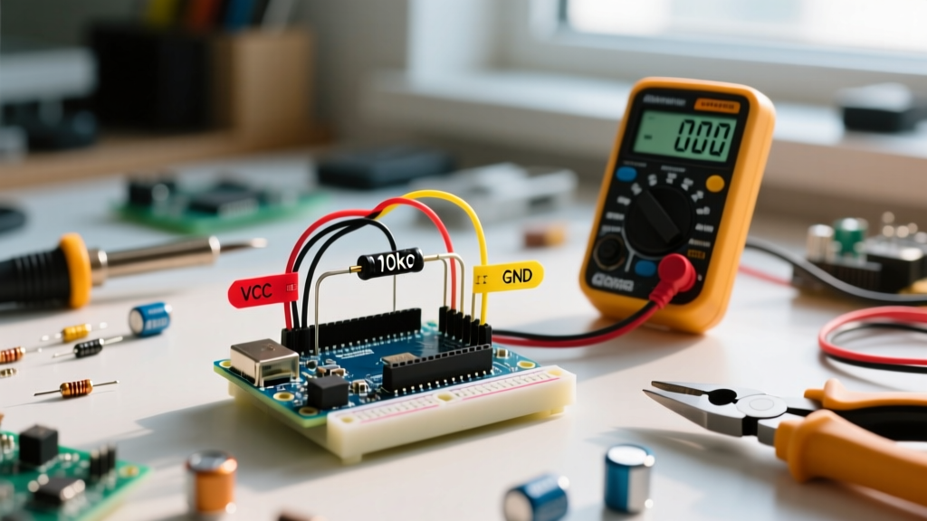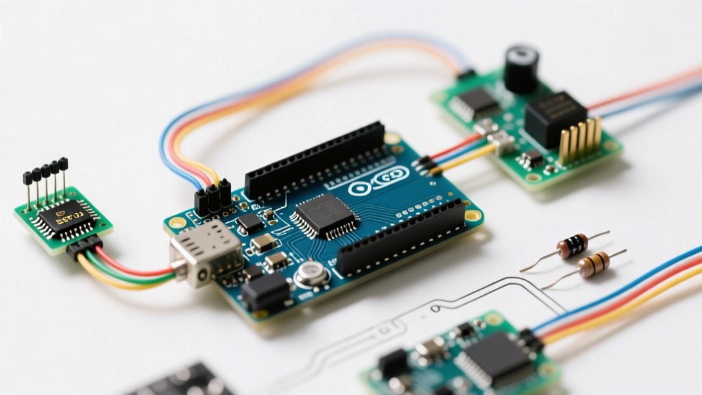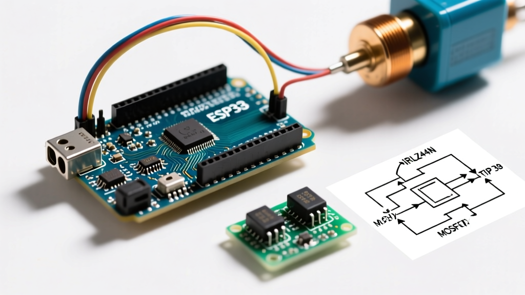

The Evolution of Solenoid Control in Maker Electronics
If you have been building electromechanical projects for more than a few months, you have likely wired a solenoid Arduino circuit using a cheap 5V relay module or a TIP120 Darlington transistor. While these legacy components are fine for blinking a 12V lock once a day, they completely fall apart in high-duty-cycle, precision, or high-current applications. As of 2026, the maker community and industrial prototyping sectors have largely standardized on logic-level N-channel MOSFETs for driving inductive loads.
This migration guide will walk you through upgrading your solenoid driver from a mechanical relay or BJT (Bipolar Junction Transistor) to a modern MOSFET architecture. You will gain PWM (Pulse Width Modulation) capability, eliminate thermal throttling, and increase your circuit's lifecycle from thousands of operations to virtually infinite solid-state switching.
The Problem with Legacy Solenoid Arduino Circuits
Before ripping out your existing wiring, it is crucial to understand the specific engineering bottlenecks of beginner-tier components.
1. Mechanical Relays (e.g., Songle SRD-05VDC-SL-C)
Most blue 5V relay modules use mechanical contacts. When driving a solenoid, which is a highly inductive load, the contacts suffer from severe arcing upon opening. This arcing degrades the metal contacts rapidly. Furthermore, relays have a mechanical lifespan of roughly 100,000 cycles. If your Arduino project actuates a pneumatic valve every 5 seconds, the relay will physically fail in less than 6 days. Finally, relays cannot handle PWM signals, making proportional solenoid control impossible.
2. The TIP120 Darlington BJT
The TIP120 is a classic beginner transistor, but it is a Darlington pair, meaning it has a notoriously high collector-emitter saturation voltage (Vce(sat)). At a modest 3A solenoid current, the TIP120 drops approximately 2.0V. That equates to 6 Watts of pure waste heat (P = V × I). Without a massive heatsink, the TO-220 package will thermal-throttle or desolder itself from the breadboard. Additionally, BJTs are current-controlled devices, requiring base resistors that waste milliamps of precious GPIO current.
The 2026 Standard: Logic-Level N-Channel MOSFETs
The modern solution is the logic-level N-channel MOSFET. Unlike standard MOSFETs that require 10V+ at the gate to fully open, logic-level variants are engineered to achieve their lowest On-Resistance (Rds(on)) at 4.5V or even 2.5V, making them perfectly compatible with the 5V logic of an Arduino Uno R4 or the 3.3V logic of an ESP32.
Expert Insight: When selecting a MOSFET for a solenoid, ignore the 'Max Drain Current' headline spec (often advertised as 60A). Instead, look strictly at the Rds(on) at Vgs = 4.5V. A lower Rds(on) means less heat and no heatsink requirement.
Component Migration Matrix (BOM)
| Component Role | Legacy (Migrate From) | Upgraded (Migrate To) | 2026 Avg. Cost | Key Advantage |
|---|---|---|---|---|
| Primary Switch | Songle 5V Relay Module | IRLB8721PBF (Logic-Level MOSFET) | $1.45 | Infinite lifecycle, PWM capable |
| Alternative Switch | TIP120 Darlington BJT | IRLZ44N (If IRLB8721 is unavailable) | $1.20 | Low Rds(on), widely available |
| Flyback Protection | 1N4007 (Standard Recovery) | 1N5819 (Schottky) or UF4007 | $0.10 | Near-zero reverse recovery time |
| Gate Protection | None (on legacy relay modules) | 100Ω Series + 10kΩ Pull-down | $0.02 | Prevents gate ringing & ghosting |
| Isolation | Optocoupler (PC817) on relay | Integrated Gate Driver or PC817 | $0.25 | Protects MCU from ground bounce |
Step-by-Step Wiring Upgrade
Migrating your physical circuit requires moving from a simple 'switch-to-ground' topology to a properly damped, protected MOSFET driver. For a deeper dive into MOSFET switching fundamentals, consult semiconductor textbooks, but follow these exact steps for your solenoid upgrade:
- Source the Inductive Kickback: Solenoids store energy in their magnetic fields. When the MOSFET turns off, this field collapses, generating a massive reverse voltage spike. You must place a flyback diode in reverse-bias across the solenoid coil (cathode to 12V, anode to the MOSFET drain). Upgrade from a 1N4007 to a 1N5819 Schottky diode; its near-instantaneous reverse recovery time clamps the spike much faster, protecting the MOSFET's internal silicon.
- Install the Gate Pull-Down Resistor: Wire a 10kΩ resistor between the MOSFET Gate and Ground. During Arduino boot-up, GPIO pins float in a high-impedance state. Without this pull-down, ambient static can partially turn on the MOSFET, causing it to overheat and fail before your sketch even starts.
- Add the Gate Series Resistor: Place a 100Ω to 220Ω resistor between your Arduino PWM pin and the MOSFET Gate. This limits the instantaneous inrush current drawn from the ATmega328P or ESP32 GPIO pin when charging the MOSFET's internal gate capacitance.
- Connect the Load: Wire the solenoid between your 12V/24V positive supply and the MOSFET's Drain. Connect the MOSFET's Source directly to the system Ground. Never put the MOSFET on the high side (positive rail) of an N-channel circuit without a dedicated gate driver.
Code Migration: From Digital to PWM Control
When using a relay, your code was limited to digitalWrite(pin, HIGH) and delay(). By upgrading to a MOSFET, you unlock analog-style proportional control. This is critical if you are upgrading to proportional solenoids (which modulate fluid pressure or force based on current) or if you want to implement a 'soft-start' to reduce mechanical shock and power supply voltage sag.
Legacy Relay Code
// Legacy: Brutal mechanical switching
const int RELAY_PIN = 8;
void setup() { pinMode(RELAY_PIN, OUTPUT); }
void loop() {
  digitalWrite(RELAY_PIN, HIGH); // Slam solenoid open
  delay(1000);
  digitalWrite(RELAY_PIN, LOW);  // Hard close
  delay(1000);
}
Upgraded MOSFET PWM Code (Soft-Start & Proportional)
// Upgraded: PWM soft-start and proportional holding
const int MOSFET_PIN = 9; // Must be a PWM-capable pin
const int RAMP_DELAY = 10; // ms per step

void setup() {
  pinMode(MOSFET_PIN, OUTPUT);
  analogWrite(MOSFET_PIN, 0); // Ensure off state
}

void loop() {
  // Soft-Start Ramp Up (Reduces inrush current & mechanical shock)
  for (int pwm = 0; pwm <= 255; pwm += 5) {
    analogWrite(MOSFET_PIN, pwm);
    delay(RAMP_DELAY);
  }

  delay(500); // Hold fully open

  // Drop to Proportional Holding Current (Saves power & reduces heat)
  analogWrite(MOSFET_PIN, 140); // ~55% duty cycle to hold
  delay(1000);

  // Ramp Down
  for (int pwm = 140; pwm >= 0; pwm -= 5) {
    analogWrite(MOSFET_PIN, pwm);
    delay(RAMP_DELAY);
  }
  delay(1000);
}
Critical Failure Modes and Edge Cases
Even with upgraded components, inductive loads are unforgiving. Watch out for these specific edge cases during your migration:
- Ground Bounce and MCU Resets: When a high-current solenoid (5A+) switches off, the sudden halt of current through shared ground traces can cause the ground potential to spike momentarily. This 'ground bounce' can reset your Arduino or corrupt I2C/SPI data. Fix: Use a star-ground topology where the solenoid power ground and the Arduino logic ground meet at exactly one physical point (usually the power supply terminals).
- Gate Ringing and Parasitic Oscillation: Long wires between the Arduino and the MOSFET gate act as antennas, picking up EMI and causing the MOSFET to rapidly oscillate between on and off states, leading to catastrophic thermal runaway. Fix: Keep the Gate series resistor physically as close to the MOSFET gate pin as possible, and keep gate wiring under 5cm in length.
- The 'Holding Current' Misconception: Solenoids require a massive inrush current to pull the plunger in, but only a fraction of that current to hold it. If you run a continuous 100% PWM duty cycle on a solenoid rated for intermittent duty, the coil insulation will melt. Always use the PWM ramp-down technique shown above to drop to a holding voltage (usually 30% to 50% of nominal) once the plunger is seated.
Summary of the Upgrade
Migrating your solenoid Arduino project from mechanical relays and BJTs to logic-level MOSFETs like the IRLB8721PBF is not just a minor component swap; it is a fundamental shift from brute-force electromechanical switching to precision solid-state control. By implementing proper flyback protection with Schottky diodes, securing the gate with pull-down resistors, and leveraging PWM for soft-starts, you ensure your 2026 builds are robust, silent, and thermally efficient.