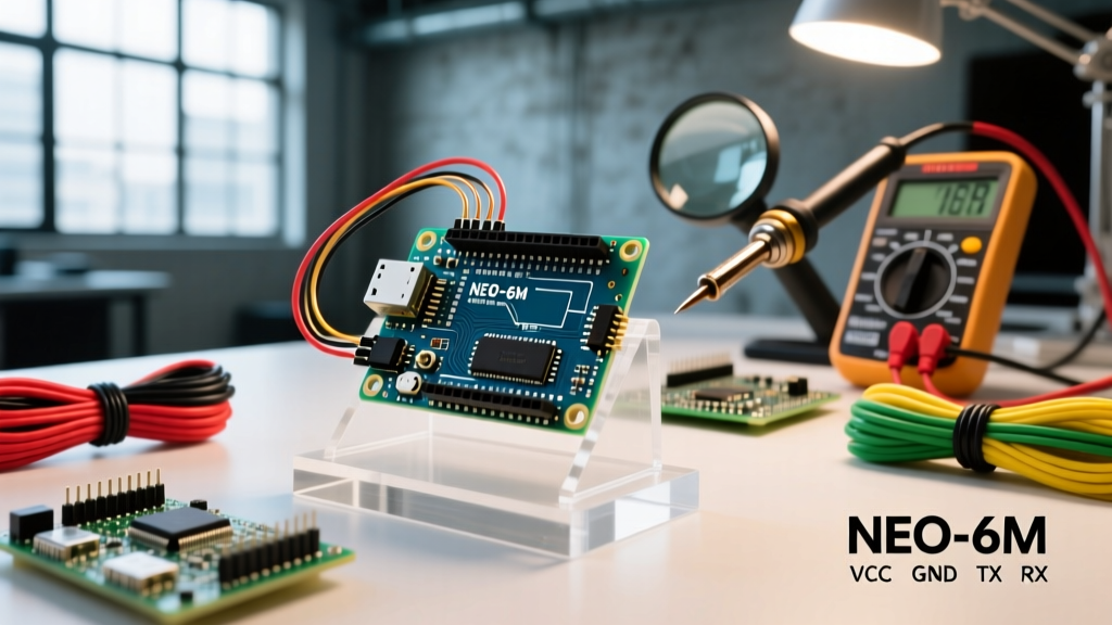

Choosing the Right GPS Arduino Module for Your Build
Integrating a GPS Arduino module into a microcontroller project requires more than just connecting four wires and uploading a sketch. Whether you are building a high-altitude balloon tracker, an autonomous rover, or a marine logging device, precise configuration of baud rates, logic levels, and NMEA sentence parsing is the difference between a reliable fix and a stream of corrupted serial garbage. As of 2026, the market is dominated by a few key chipsets, each with distinct configuration requirements.
| Module | Chipset | Avg. Price (2026) | Logic Level | Default Baud | Best Use Case |
|---|---|---|---|---|---|
| Generic NEO-6M | u-blox NEO-6M | $10 - $14 | 3.3V (Strict) | 9600 | Budget trackers, basic logging |
| Adafruit Ultimate GPS | MediaTek MTK3339 | $40 - $45 | 3.3V (Tolerant) | 9600 | Precision timing (PPS), robotics |
| u-blox SAM-M8Q | u-blox M8 | $25 - $30 | 3.3V (Strict) | 9600 / I2C | Multi-GNSS, drone flight controllers |
The 5V to 3.3V Logic Level Trap
The most common point of failure in GPS Arduino configurations is ignoring logic level shifting. The vast majority of modern GPS modules, including the ubiquitous NEO-6M and the MTK3339-based boards, operate at 3.3V logic. Connecting the TX pin of a 5V Arduino Uno directly to the RX pin of a 3.3V GPS module will slowly degrade the module's internal silicon, eventually leading to permanent failure.
Building a Reliable Voltage Divider
While the GPS module's TX pin can usually be read directly by a 5V Arduino's RX pin (since 3.3V is recognized as a logical HIGH by 5V ATmega328P chips), the Arduino's TX pin must be stepped down before reaching the GPS RX pin. The most cost-effective and reliable method is a simple resistor voltage divider.
- R1 (Series Resistor): 10kΩ connected to Arduino TX.
- R2 (Ground Resistor): 20kΩ connected between GPS RX and GND.
- Junction: The point where R1 and R2 meet connects to the GPS RX pin.
Using the voltage divider formula Vout = Vin * (R2 / (R1 + R2)), a 5V signal is reduced to exactly 3.33V, which is perfectly within the safe operating margin for the u-blox NEO-6 series and MTK chipsets.
Hardware vs. Software Serial Configuration
How you configure the serial interface drastically impacts your sketch's reliability. The SoftwareSerial library is frequently used in beginner tutorials to free up the hardware serial pins (Pins 0 and 1) for debugging via the Serial Monitor. However, SoftwareSerial has severe limitations.
Expert Warning: SoftwareSerial disables interrupts while listening for incoming data. If your GPS Arduino project also utilizes NeoPixel LEDs, servo motors, or rotary encoders, SoftwareSerial will cause severe timing glitches and data loss. Always prefer HardwareSerial on boards that support multiple UARTs, such as the Arduino Mega, Leonardo, or ESP32.
If you must use an Arduino Uno, configure SoftwareSerial on pins that support pin-change interrupts (e.g., Pins 10 and 11). More importantly, do not attempt to run SoftwareSerial at 115200 baud. The software timing cannot reliably sample bits at that speed on a 16MHz AVR chip, resulting in fragmented NMEA sentences. Lock your GPS module to 9600 or 19200 baud when using software emulation.
Initializing the Serial Stream
Here is the optimal initialization sequence for an Arduino Mega using HardwareSerial1, avoiding the SoftwareSerial overhead entirely:
#include <TinyGPSPlus.h>
TinyGPSPlus gps;

void setup() {
  Serial.begin(115200); // Debugging monitor
  Serial1.begin(9600);  // Hardware UART for GPS
}

void loop() {
  while (Serial1.available() > 0) {
    if (gps.encode(Serial1.read())) {
      // Process new NMEA data
    }
  }
}
Optimizing Baud Rates and Update Frequencies
Out of the box, most modules output NMEA sentences at 1Hz (one update per second) at 9600 baud. For high-speed applications like RC planes or autonomous rovers, 1Hz is insufficient. You must send specific configuration strings to the module to increase the update rate.
Configuring the MTK3339 (Adafruit Ultimate GPS)
The MediaTek chipset uses PMTK (Packet Type, Message, Keyword) commands. To increase the update rate to 5Hz, you send the following string via the Arduino's TX pin during the setup() loop:
Serial1.println("$PMTK220,200*2C");
The 200 represents 200 milliseconds between updates. Note that pushing the MTK3339 to 10Hz (100ms) requires disabling certain NMEA sentences to prevent the serial buffer from overflowing at 9600 baud. The Adafruit Ultimate GPS Learning Guide provides a comprehensive matrix of PMTK checksums for sentence filtering.
Configuring the u-blox NEO-6M
u-blox modules do not use PMTK; they use UBX binary protocols or specific NMEA configuration sentences. To change the baud rate of a NEO-6M to 19200, you must send a UBX-CFG-PRT packet. Because calculating the Fletcher checksum for UBX binary packets manually is error-prone, it is highly recommended to use the u-center software via a USB-to-Serial FTDI adapter to configure the module's EEPROM before connecting it to your Arduino. Once saved to the module's non-volatile memory, the Arduino will automatically handshake at the new baud rate.
NMEA Parsing: TinyGPS++ vs. Adafruit_GPS
Raw NMEA 0183 data is a continuous stream of comma-separated text strings. Parsing this manually using String manipulation in C++ will quickly fragment your Arduino's SRAM, leading to memory leaks and system crashes. You must use a dedicated parsing library.
Why TinyGPS++ is the Industry Standard
Mikal Hart's TinyGPS++ Library Reference remains the gold standard for AVR-based Arduinos. Unlike older libraries that buffer entire NMEA sentences in RAM, TinyGPS++ processes the serial stream character-by-character. This zero-allocation approach is critical for the ATmega328P, which only has 2KB of SRAM.
When configuring TinyGPS++, you can extract specific data points without parsing the entire sentence payload:
- gps.location.lat(): Extracts latitude from the GGA and RMC sentences.
- gps.altitude.meters(): Extracts altitude (only available in GGA sentences).
- gps.speed.kmph(): Extracts ground speed (only available in RMC sentences).
- gps.satellites.value(): Returns the number of tracked satellites.
Troubleshooting Edge Cases: Cold Starts and Indoor Fixes
Even with perfect wiring and code, GPS Arduino projects frequently fail during initial testing due to environmental and hardware edge cases. Understanding these failure modes will save you hours of debugging.
The 'No Fix' Indoor Syndrome
GPS signals operate at roughly 1.575 GHz with a transmission power of -130 dBm by the time they reach Earth's surface. This signal is weaker than the thermal noise floor of the receiver. It cannot penetrate concrete, metal roofs, or even heavy wet foliage. You must test your initial configuration outdoors with a clear view of the sky. Testing on a workbench indoors will result in a perpetual 'No Fix' state, leading many makers to falsely conclude their module is defective.
Cold Starts and the Backup Battery
When a GPS module powers on without a valid almanac and ephemeris stored in its RAM, it performs a 'Cold Start'. The module must blindly search the sky for satellite Doppler shifts, download the orbital data, and calculate a fix. This process can take anywhere from 15 to 30 minutes.
To prevent a cold start on every power cycle, modules include a V_BAK (Backup Voltage) pin. On the NEO-6M, this is usually tied to a CR1220 coin cell or a supercapacitor on the breakout board. If your GPS Arduino setup takes 20 minutes to get a fix every time you turn it on, check the voltage of the backup battery. If it is dead, the module loses its orbital cache the moment main power is cut. Replacing the battery or ensuring the supercapacitor is charging properly will reduce subsequent 'Warm Starts' to under 30 seconds.
Antenna Impedance and Placement
The ceramic patch antenna included with budget NEO-6M modules is highly directional. It must face the sky directly. Furthermore, the antenna relies on a ground plane to achieve its 50-ohm impedance match. If you mount the GPS module inside a plastic enclosure, ensure the patch antenna is at the very top. If you are using an external active antenna via a U.FL connector, ensure the coaxial cable is kept away from high-frequency digital lines (like SPI or I2C buses) on your custom PCB to prevent harmonic interference that desensitizes the GPS LNA (Low Noise Amplifier).
Final Configuration Checklist
Before deploying your GPS Arduino project into the field, verify the following parameters:
- Logic levels are shifted (5V TX to 3.3V GPS RX).
- HardwareSerial is used instead of SoftwareSerial whenever possible.
- Baud rate in the sketch matches the module's firmware configuration (usually 9600).
- Unnecessary NMEA sentences are disabled to save serial bandwidth if running above 1Hz.
- Backup battery voltage is verified to ensure warm starts.
By adhering to these hardware and software configuration standards, your microcontroller will reliably parse global positioning data, forming a robust foundation for any navigation or tracking application.