
The Physics of the Knob: Voltage Division
When makers first start experimenting with analog inputs, the standard 10kΩ rotary potentiometer (often labeled B10K) is universally the first component they wire up. But treating a potentiometer merely as a 'knob' ignores the foundational electrical engineering concept at play: the voltage divider. A potentiometer is fundamentally a three-terminal resistor with a continuously adjustable sliding or rotating contact (the wiper). When you apply a reference voltage (VCC) across the two outer terminals, the wiper acts as a movable tap, outputting a variable voltage proportional to its physical position.
According to All About Circuits, the output voltage ($V_{out}$) is dictated by the ratio of the resistance between the wiper and ground ($R_2$) to the total resistance ($R_{total}$). If you supply 5V to a 10kΩ potentiometer and turn the shaft to the exact mechanical center, $R_1$ and $R_2$ both equal 5kΩ, yielding a precise 2.5V output at the wiper. This continuous analog voltage is what the microcontroller ultimately measures.
Inside the Microcontroller: ADC and Source Impedance
The Arduino cannot read continuous analog voltages directly. Instead, it relies on an Analog-to-Digital Converter (ADC) to sample the voltage and translate it into a discrete binary number. Classic 5V boards like the Uno R3 and Mega 2560 use the ATmega328P or ATmega2560 microcontrollers, which feature a 10-bit Successive Approximation Register (SAR) ADC. This 10-bit resolution means the 0-5V range is sliced into 1,024 discrete steps (0 to 1023). Each step represents approximately 4.88 millivolts ($5V / 1024$).
Modern 3.3V ecosystems, such as the Nano ESP32, Raspberry Pi Pico (RP2040), and ESP32-S3 DevKitC, typically utilize 12-bit ADCs, offering 4,096 steps across a narrower 0-3.3V range (approx 0.8 millivolts per step). As noted in the official Arduino analogRead() documentation, the function abstracts these hardware differences, automatically mapping the raw ADC register values to a standard 0-1023 range for backward compatibility, though you can access the raw 12-bit data using lower-level registers or specific core functions like analogReadResolution(12) on supported SAMD and ESP32 architectures.
The 10kΩ Rule and Sample-and-Hold Capacitors
A critical, often overlooked specification when using a potentiometer on Arduino is source impedance. Inside the ATmega328P, the ADC uses a tiny internal sample-and-hold capacitor (approximately 14pF) to capture the voltage snapshot. If your potentiometer has too high a resistance (e.g., a 100kΩ or 1MΩ pot), the internal capacitor cannot charge fast enough during the brief sampling window (roughly 1.5 ADC clock cycles). This results in artificially low, inaccurate readings. Microchip's datasheets recommend keeping the source impedance at 10kΩ or lower. Therefore, a standard B10K (10,000 ohm linear taper) potentiometer, such as the Bourns PTV09A series, is the mathematically optimal choice for 5V Arduino boards.
Choosing the Right Taper: Linear vs. Logarithmic
Potentiometers are manufactured with different resistance 'tapers', which define how the resistance changes relative to the shaft's physical rotation. Selecting the wrong taper will result in non-linear, frustrating user inputs.
| Taper Type | Marking | Resistance Curve | Best Arduino Use Case |
|---|---|---|---|
| Linear | B (e.g., B10K) | Resistance changes at a constant rate. 50% rotation = 50% resistance. | Position sensing, menu navigation, PID tuning, servo control. |
| Logarithmic (Audio) | A (e.g., A10K) | Resistance changes slowly at first, then rapidly. Matches human hearing. | Analog audio volume control (pre-ADC). Largely obsolete for MCU inputs since software mapping can simulate this curve. |
| Anti-Logarithmic | C (e.g., C10K) | Reverse of logarithmic. Rapid change early, slow change later. | Specific sensor calibration curves, reverse-audio compensation. |
Expert Tip: Always buy B-taper (Linear) potentiometers for Arduino projects. If you need a logarithmic response for a UI element (like a volume slider on an OLED screen), use a linear B10K pot and apply a logarithmic mapping function in your C++ code. Hardware log tapers are notoriously difficult to map predictably in software due to manufacturing tolerances.
Wiring a Potentiometer on Arduino (5V vs 3.3V Logic)
Wiring is straightforward, but voltage mismatches in 2026's mixed-logic maker environment frequently destroy microcontroller pins. Follow these strict wiring protocols:
- Pin 1 (CCW / Ground): Connect to the microcontroller's GND.
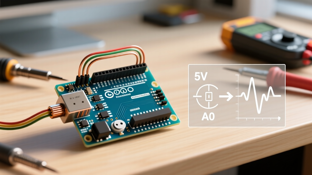
- Pin 2 (Wiper / Signal): Connect to an Analog Input pin (e.g., A0). This is your signal output.
- Pin 3 (CW / VCC): Connect to the microcontroller's logic voltage.
CRITICAL WARNING for 3.3V Boards: If you are using an ESP32, Nano 33 BLE, or Raspberry Pi Pico, you MUST connect Pin 3 to the 3.3V output, NOT the 5V (VIN) pin. Supplying 5V to the wiper of a pot connected to a 3.3V-tolerant ADC pin will exceed the absolute maximum ratings and permanently degrade or destroy the GPIO silicon.
Solving ADC Jitter: Hardware and Software Filtering
Even with a perfect B10K potentiometer, you will notice that analogRead(A0) rarely returns a perfectly stable number. At a resting position, the serial monitor might show values jumping erratically: 512, 515, 510, 514. This 'jitter' is caused by electromagnetic interference (EMI), thermal noise in the carbon track, and power supply ripple from the USB connection. As explained in SparkFun's comprehensive guide on ADCs, high-impedance analog traces act as antennas, picking up ambient 50/60Hz mains hum and switching noise from nearby digital traces.
The Hardware Fix: The 100nF Bypass Capacitor
Before writing complex filtering code, fix the physics. Solder a 100nF (0.1µF) X7R ceramic capacitor directly between the Wiper pin (Signal) and GND, as physically close to the microcontroller pin as possible. This creates a low-pass RC filter. Combined with the 10kΩ output impedance of the pot's upper half, this yields a cutoff frequency of roughly 159Hz, effectively shorting high-frequency digital noise to ground while allowing the slow, deliberate movements of the human hand to pass through to the ADC.
The Software Fix: Exponential Moving Average (EMA)
If hardware filtering isn't enough, or if you are constrained by PCB space, implement an Exponential Moving Average (EMA) filter in your sketch. Unlike a simple rolling average that requires storing an array of past values (consuming precious SRAM), an EMA uses a single floating-point or integer variable to smooth the data with minimal computational overhead.
// EMA Filter Implementation for Potentiometer Smoothing
const int potPin = A0;
float smoothedValue = 0;
const float alpha = 0.05; // Smoothing factor (0.0 to 1.0). Lower = smoother but more lag.

void setup() {
  Serial.begin(115200);
  smoothedValue = analogRead(potPin); // Initialize with first reading
}

void loop() {
  int rawValue = analogRead(potPin);

  // EMA Formula: S_t = alpha * X_t + (1 - alpha) * S_t-1
  smoothedValue = (alpha * rawValue) + ((1.0 - alpha) * smoothedValue);

  Serial.println((int)smoothedValue);
  delay(10); // 10ms polling rate
}
By combining a 10kΩ linear taper potentiometer, a 100nF ceramic bypass capacitor, and an EMA software filter, you transform a noisy, jittery analog input into a rock-solid, precision control interface suitable for everything from CNC machine jog wheels to synthesizer MIDI controllers.