
The Ultimate Quick Reference for Arduino Sizes and Dimensions
When designing custom enclosures, ordering PCBs for shields, or planning a permanent embedded installation, guessing your Arduino sizes is a recipe for disaster. A millimeter of miscalculation can result in misaligned USB ports, crushed surface-mount components, or mounting holes that fail to line up with your standoffs. Whether you are 3D printing a custom PETG case or integrating a microcontroller into an industrial control panel, knowing the exact mechanical footprint of your board is critical.
In this quick reference guide, we break down the exact physical dimensions, mounting hole spacings, and form factor quirks of the most popular Arduino boards available in 2026. We will also cover critical edge cases—like breadboard incompatibilities and shield stacking clearances—that rarely make it into standard spec sheets.
Arduino Sizes: Quick Reference Dimension Table
The table below provides the baseline mechanical specifications for official Arduino boards. Note that Height refers to the PCB and surface-mount components only, excluding male pin headers and tall electrolytic capacitors.
| Board Model | Length (mm) | Width (mm) | Height (mm) | Mounting Holes | Typical Price (2026) |
|---|---|---|---|---|---|
| Uno R4 Minima / WiFi | 68.6 mm | 53.4 mm | 11.5 mm | 4x M3 (3.2mm dia) | $20.00 - $27.50 |
| Nano (Classic / Every) | 45.0 mm | 18.0 mm | 7.0 mm | None | $22.00 - $24.50 |
| Mega 2560 Rev3 | 101.5 mm | 53.3 mm | 12.0 mm | 4x M3 + 1x M3 (Center) | $45.00 - $49.00 |
| Micro | 48.0 mm | 18.0 mm | 7.0 mm | None | $21.00 |
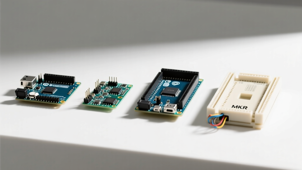
| MKR WiFi 1010 | 61.5 mm | 25.0 mm | 8.5 mm | None (Castellated) | $35.00 - $38.00 |
| Portenta H7 | 66.0 mm | 25.0 mm | 9.0 mm | None (High-Density) | $105.00+ |
Form Factor Deep Dives & Mechanical Quirks
The Uno Standard: Shield Compatibility & Overhangs
The Arduino Uno R4 WiFi Official Documentation confirms that the modern R4 series retains the exact 68.6 x 53.4 mm footprint of the legacy R3. This ensures backward compatibility with thousands of third-party shields. However, enclosure designers must account for the connector overhang. The USB-C port and the DC power jack extend approximately 11.5 mm beyond the edge of the PCB. If your 3D printed enclosure wall is flush with the PCB edge, your cables will not seat properly. Always add a 12mm cutout recess or extend the enclosure wall outward.
Mounting Hole Spacing: The four corner mounting holes are spaced 48.26 mm apart horizontally and 43.18 mm apart vertically. Use M3 (3mm) screws with nylon washers to prevent shorting the ground planes located near the hole vias.
The Nano & Micro: The Breadboard Spacing Problem
At 45 mm x 18 mm, the Nano is a favorite for prototyping. However, its width introduces a notorious mechanical headache. The distance between the two rows of male headers is exactly 15.24 mm (0.6 inches). A standard solderless breadboard features a center gap of 7.62 mm (0.3 inches) flanked by 5-hole rows. If you attempt to straddle the center gap, the pins would need to be spaced at 17.78 mm (0.7 inches) to land in the 'c' and 'h' rows. Because the Nano is 0.6 inches wide, it does not align with standard breadboard grids when straddling the center gap. Makers must either plug it into one side of the board (hanging off the edge) or use specialized adapter boards. For permanent installs, the Nano lacks mounting holes, requiring friction-fit 3D printed clips or hot glue.
The Mega 2560: Industrial Footprints
According to the Arduino Mega 2560 Hardware Specs, the board stretches to 101.5 mm in length to accommodate the ATmega2560 chip and 70 I/O headers. The critical design feature here is the fifth mounting hole located near the center of the board, directly between the digital pins and the secondary I2C/UART headers. When designing CNC-machined aluminum backplates for industrial enclosures, omitting this center standoff often leads to board flex when users press down on the right-side header pins during wiring.
MKR & Portenta: The 25mm IoT Standard
The MKR family and the high-end Portenta H7 share a 25 mm width. This is not an arbitrary number; 25 mm is the standard width of common single-cell LiPo batteries and fits perfectly into standard DIN-rail mounting modules. Unlike the Uno, these boards rely on castellated edges or high-density PCIe-style connectors rather than standard 0.1-inch female headers, drastically reducing the Z-axis height when designing ultra-slim wall-mounted IoT sensors.
Pro-Tip for PCB Designers: If you are designing a custom carrier board for the Nano or Micro, do not place SMD components directly beneath the board's footprint. The solder joints on the underside of the Nano's pin headers can protrude up to 1.5 mm, risking a short circuit against your carrier board's top-layer traces.
Enclosure Design & 3D Printing Tolerances
When translating Arduino sizes into CAD models (Fusion 360, SolidWorks, or Tinkercad), applying exact dimensions will result in a failed print. FDM 3D printing introduces material shrinkage and elephant's foot effects. Follow these tolerance rules:
- PCB Slot Clearances: Add 0.2 mm to 0.3 mm of clearance on all X and Y axes for the PCB slide-in slots. A 53.4 mm wide Uno needs a 53.8 mm slot.
- Standoff Interference: If using printed standoffs instead of metal ones, make the hole diameter 3.4 mm for an M3 screw to allow for self-tapping, or 3.1 mm if using a brass heat-set insert.
- Header Height (Z-Axis): Standard male breakaway headers add 11.5 mm to the top of the PCB. If stacking a shield, add another 10.5 mm for the female header housing, plus 1.5 mm for the shield PCB itself. Plan for at least 25 mm of internal Z-clearance above the Uno PCB.
Frequently Asked Questions (FAQ)
Are all Uno clone boards the exact same size?
Most reputable clones (like those from Elegoo or MakerHawk) strictly adhere to the 68.6 x 53.4 mm footprint to guarantee shield compatibility. However, some budget clones use stamped USB-B connectors that protrude 1-2 mm further than the official molded connectors, and their DC jacks may sit slightly higher. Always measure your specific clone batch before mass-producing an enclosure.
Do the Arduino Nano and Micro share the same dimensions?
No. While both share an 18 mm width, the Arduino Nano Mechanical Drawings show a length of 45 mm, whereas the Micro is 48 mm long. Furthermore, the Micro includes a Micro-USB (or USB-C on newer revisions) connector that overhangs the PCB edge, while the Nano's Mini-USB or USB-C connector sits flush or slightly recessed depending on the manufacturer. They are not interchangeable in tight-fitting enclosures.
How do I mount a Nano without mounting holes?
The most reliable method is to use a 3D-printed 'sled' or friction-fit clip that grips the edges of the PCB, avoiding pressure on the USB connector. Alternatively, you can solder female headers to your main PCB and plug the Nano in, using the tension of the 30 pins to hold it in place, secured with a dab of RTV silicone on the corners for vibration resistance.
What is the maximum weight an Arduino mounting hole can support?
The FR4 fiberglass PCB material and the copper plating around the vias can handle significant static loads, but the limiting factor is the screw head. Using a standard M3 pan-head screw with a 6mm nylon washer distributes the load safely. For heavy shield stacks (e.g., Uno + Motor Shield + GPS Shield), always use the center standoff on the Mega, or add a secondary support bracket under the shields to prevent the PCB from bowing and cracking the ceramic capacitors near the power regulation circuitry.