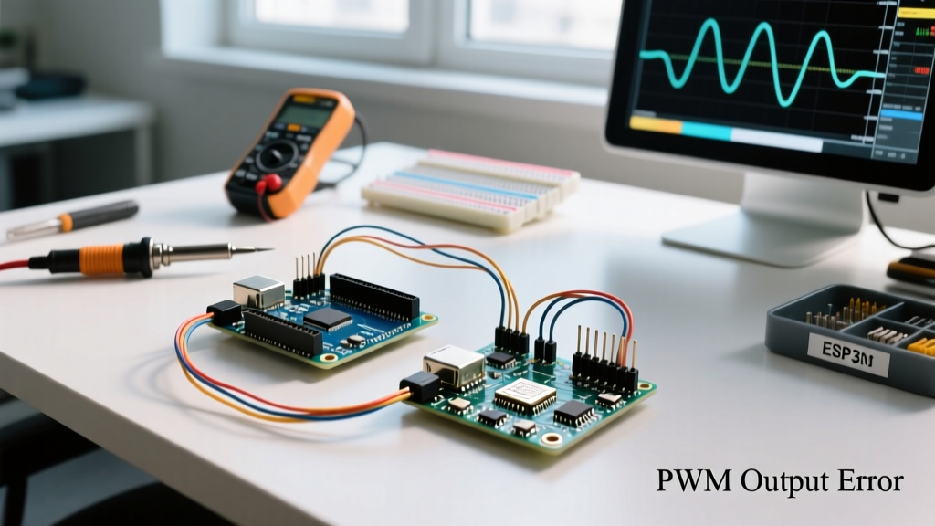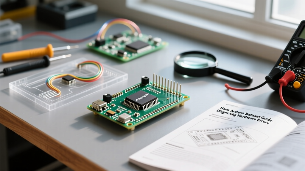

When an Arduino Nano fails in the field or refuses to accept a new sketch, the Arduino IDE error log only tells half the story. Software timeouts and compilation warnings are often symptoms of underlying hardware limitations or physical failures. To truly master error diagnosis, makers and engineers must look beyond the IDE and consult the nano arduino datasheet—along with the datasheets of its supporting silicon. By understanding the absolute maximum ratings, power tree architecture, and serial interface timing, you can rapidly isolate whether a failure stems from a brownout, a bootloader corruption, or a peripheral bus conflict.
The Core Silicon: ATmega328P vs. ATmega168 Limitations
The most common point of confusion when diagnosing memory-related crashes or silent upload failures is the specific microcontroller variant on your board. While the official Arduino Nano documentation specifies the Microchip ATmega328P, the market is flooded with older or cheaper variants. If your sketch compiles but immediately resets upon execution, you are likely hitting SRAM limits or watchdog timer conflicts dictated by the silicon.
Silicon Variant Comparison Matrix
| Parameter | ATmega328P (Standard) | ATmega168 (Legacy/Clone) | Diagnostic Symptom of Limit |
|---|---|---|---|
| Flash Memory | 32 KB (30.5 KB usable) | 16 KB (15.5 KB usable) | 'Sketch too big' or silent bootloader overwrite |
| SRAM | 2 KB | 1 KB | Random reboots, String class crashes |
| EEPROM | 1 KB | 512 Bytes | Data corruption on high-address writes |
| Bootloader Footprint | Optiboot (512 Bytes) | ATmegaBOOT (2 KB) | Upload timeouts on mismatched board profiles |
Diagnostic Action: If you encounter erratic behavior with heavy String manipulations or large buffer arrays, verify your chip. Many budget boards from 2024-2026 still use salvaged ATmega168 chips. Selecting 'Arduino Nano' in the IDE defaults to the 328P; if your board has a 168, you must select 'ATmega168' under the Tools > Processor menu, or the Optiboot bootloader parameters will mismatch, causing immediate runtime crashes.
Power Regulation Failures and Brownout Detection (BOD)
A frequent hardware error on the Nano is the 'phantom reset,' where the board restarts without a software trigger. This is almost always a power regulation issue governed by the microcontroller's Brown-out Detection (BOD) fuse bits. According to the Microchip ATmega328P datasheet, the BOD is typically factory-set to trigger at 2.7V or 4.3V.
Decoding the Nano Power Tree
The Nano's power routing is a common trap for intermediate makers. The board features a 5V pin and a VIN pin, but they behave very differently under load:
- USB Power (5V Pin): Power is routed through a Schottky diode (typically an MBR0520) from the USB bus. This limits the 5V pin output to roughly 4.7V. If your BOD is set to 4.3V, you have only a 0.4V noise margin. Heavy sensor loads pulling >200mA will cause voltage sag, tripping the BOD and resetting the MCU.
- VIN Pin (Onboard LDO): Powering via VIN routes through an onboard Low Dropout Regulator (LDO). In genuine 2026 boards, this is often a SOT-23-5 package LDO like the ME6211C50. Without a heatsink, this LDO will enter thermal shutdown at currents exceeding 120mA-150mA when dropping 9V to 5V.
Expert Diagnostic Tip: If your Nano resets when a servo motor or relay activates, do not just add a larger capacitor. Use a multimeter to measure the 5V pin during the load spike. If it dips below 4.1V, you are tripping the BOD. Bypass the onboard regulator entirely by feeding a regulated 5V source directly into the 5V pin, bypassing the USB diode and VIN LDO limitations.
USB-to-Serial Interface Errors: FT232RL vs. CH340/CH343
The dreaded avrdude: stk500_recv(): programmer is not responding error is rarely a microcontroller failure; it is a breakdown in the USB-to-Serial handshake. The Nano Arduino datasheet schematic reveals a critical auto-reset circuit that bridges the USB interface chip and the ATmega328P's RESET pin.
The Auto-Reset Capacitor Diagnosis
To enter the bootloader, the USB interface chip must pulse the RESET pin LOW for exactly 10 to 50 milliseconds. This is achieved via a 100nF series capacitor connected between the DTR (Data Terminal Ready) line and the RESET pin, which is held HIGH by a 10kΩ pull-up resistor.
- The Genuine FT232RL Era: Older, genuine Nanos used the FTDI FT232RL. As noted in the FTDI FT232RL product documentation, the DTR timing is hardware-controlled and highly precise. These boards cost upwards of $24 in 2026.
- The CH340G Clone Standard: Most clones use the WCH CH340G. The DTR pulse timing on the CH340G is slightly slower and relies heavily on the host OS driver. If the 100nF capacitor on your clone board has degraded (common in high-humidity environments), the RC time constant shifts, and the RESET pulse becomes too short to trigger the bootloader.
- The 2026 CH343G Shift: Newer high-speed clones are adopting the CH343G chip. While faster, early 2026 driver implementations on Linux and macOS occasionally mishandle the DTR assertion, resulting in upload timeouts.
Diagnostic Action: Connect an oscilloscope or a logic analyzer to the RESET pin while clicking 'Upload' in the IDE. You should see a sharp drop to 0V lasting roughly 20ms. If the drop is only 2ms, your 100nF capacitor is failing or the USB driver is cutting the DTR signal short. Soldering a fresh 100nF (0.1µF) ceramic capacitor across the DTR and RESET pins resolves 90% of stubborn clone upload errors.
I/O Pin Limits and Peripheral Bus Lockups
Hardware lockups where the I2C bus (A4/A5) freezes are often traced back to violating the absolute maximum ratings outlined in the silicon datasheet. The ATmega328P specifies an absolute maximum of 40mA per I/O pin, but a strict 200mA total limit for the VCC and GND pins combined.
If you are driving multiple I2C sensors without external pull-ups, or if you are back-powering the board through an I/O pin (a common mistake when wiring displays), you risk activating the internal ESD protection diodes. Once these diodes conduct, they inject current directly into the substrate, causing the MCU to latch up or the I2C state machine to freeze.
Step-by-Step I2C Lockup Recovery
- Step 1: Disconnect all peripherals from A4 (SDA) and A5 (SCL).
- Step 2: Measure the resistance from A4/A5 to GND. A reading below 2kΩ indicates a blown internal ESD diode or a shorted peripheral.
- Step 3: If the MCU is fine but the bus is locked, the slave device is likely holding SDA LOW. Implement a software I2C bus recovery routine in your setup() function that toggles the SCL pin manually 9 times to force the slave to release the bus.
Frequently Asked Questions
Why does my Nano get excessively hot when powered via VIN?
The onboard LDO is dissipating the voltage difference as heat. If you supply 12V to VIN and draw 100mA from the 5V pin, the LDO must dissipate (12V - 5V) * 0.1A = 0.7 Watts. The SOT-23-5 package lacks the thermal mass to handle this, triggering thermal shutdown. Always use a switching buck converter to drop voltage to 5V before feeding it into the 5V pin.
Can I use the TX/RX pins (D0/D1) while uploading a sketch?
No. The TX and RX pins are hardwired to the USB-to-Serial interface. Connecting external devices that pull these pins HIGH or LOW will interfere with the serial data stream, causing checksum errors during the avrdude upload process. Use SoftwareSerial on other digital pins if you need concurrent debugging.
How do I check if the bootloader is corrupted?
Connect an ISP programmer (like a USBasp) to the ICSP header. Use the 'Burn Bootloader' function in the IDE. If the board immediately begins functioning normally via USB afterward, the previous bootloader flash was corrupted, likely due to a power loss during a prior upload attempt or a faulty flash memory cell.