
The Reality of Microcontroller Audio
Getting a microcontroller to blink an LED is trivial; getting it to output clean, high-fidelity audio is a notorious rite of passage for embedded engineers. When you attempt to play sound from Arduino, you are immediately confronted with hardware limitations: lack of native digital-to-analog converters (DACs), 5V logic level mismatches, and severe power supply transient issues. Whether you are building a retro synthesizer, an interactive art installation, or a simple MP3 player, audio bugs usually manifest as aggressive buzzing, complete silence, or random system brownouts.
This comprehensive troubleshooting guide dissects the three most common methods to play sound from Arduino—direct PWM, the DFPlayer Mini MP3 module, and I2S DACs—and provides exact, component-level fixes for the failures you will encounter in 2026 and beyond.
Method 1: Direct PWM Audio (The 490Hz Whine)
The most basic way to play sound from Arduino is using Pulse Width Modulation (PWM) via the analogWrite() function or the official Arduino Tone library. However, users frequently report a maddening, high-pitched whine overlaying their audio track.
The Root Cause: Default Timer Frequencies
On the standard Arduino Uno (ATmega328P), pins 5, 6, 9, and 10 operate at a default PWM frequency of roughly 490Hz, while pins 3 and 11 operate at 980Hz. Because these frequencies fall squarely within the human hearing range (20Hz to 20kHz), your speaker or amplifier will reproduce the PWM carrier wave as a loud, continuous buzz.
Software Fix: Pushing to Ultrasonic Frequencies
To eliminate the carrier whine, you must push the PWM frequency above human hearing (ideally >31kHz). If you are using an AVR-based board, install the TimerOne library via the Library Manager. By taking control of Timer1, you can safely drive Pin 9 or 10 at 31.25kHz.
- Initialization:
Timer1.initialize(32);(Sets period to 32 microseconds). - Output:
Timer1.pwm(9, 512);(Outputs 50% duty cycle on Pin 9).
Note: For 32-bit ARM boards like the Arduino Nano 33 IoT or Teensy 4.1, use the native analogWriteResolution(12) and analogWriteFrequency() functions to configure hardware DACs or high-resolution PWM without third-party timer libraries.
Hardware Fix: The RC Low-Pass Filter
Even at 31kHz, raw PWM is a square wave rich in odd harmonics. Before feeding this signal into an amplifier like the PAM8403, you must smooth it into a sine-like analog wave using a passive RC (Resistor-Capacitor) low-pass filter.
Expert Build Spec: Solder a 1kΩ resistor in series with your PWM output pin, followed by a 10nF (0.01µF) ceramic capacitor tied from the resistor's output leg to Ground. This creates a cutoff frequency of approximately 15.9kHz, effectively stripping the ultrasonic carrier while preserving the audible audio spectrum.
Method 2: DFPlayer Mini MP3 Module Failures
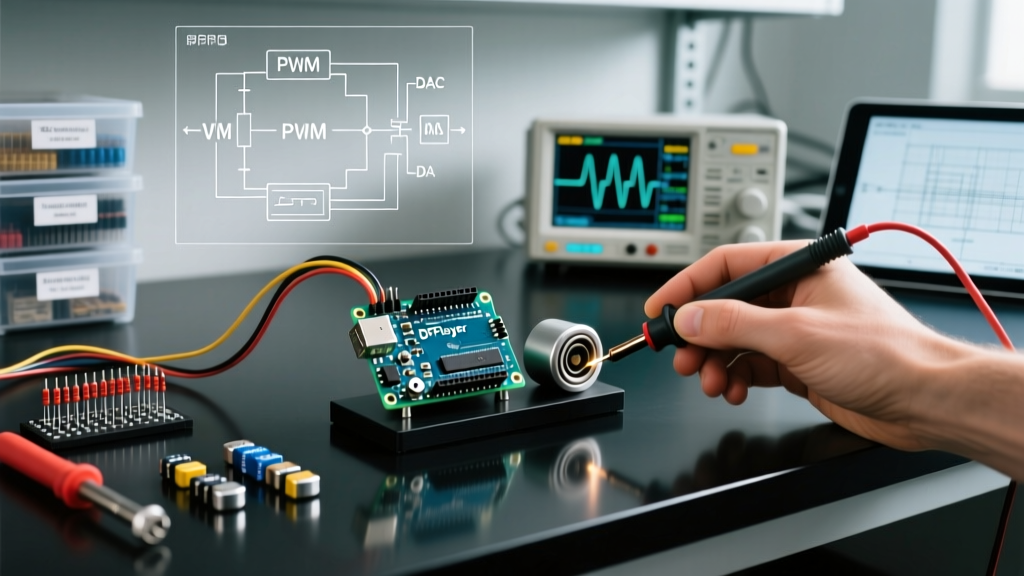
The DFPlayer Mini is a $3 serial-controlled MP3 module that reads directly from a microSD card. While the DFRobot DFPlayer Mini documentation is extensive, makers consistently run into three specific failure modes when trying to play sound from Arduino using this board.
Troubleshooting Matrix: DFPlayer Mini
| Symptom | Root Cause | Exact Hardware/Software Fix |
|---|---|---|
| Module ignores serial commands; no audio. | 5V logic from Arduino TX is overloading the 3.3V RX pin on the DFPlayer, causing internal logic lockup or silicon damage. | Insert a 1kΩ resistor in series between the Arduino TX pin and the DFPlayer RX pin to drop the voltage to safe 3.3V levels. |
| Module initializes, but returns "File Not Found" errors. | MicroSD card is formatted as exFAT or NTFS, or folder naming conventions are violated. | Format SD card to FAT32 (max 32GB) with a 4096-byte allocation unit size. Folders must be named 01, 02, and files 001.mp3. |
| Audio plays, but is accompanied by a loud 50/60Hz hum. | Ground loop created by sharing power rails between the digital MCU and the analog audio amplifier. | Power the DFPlayer from a separate 5V rail, or use a star-grounding topology where the MCU ground and Amp ground meet at a single physical point. |
Method 3: I2S DACs (MAX98357A / PCM5102)
For high-fidelity, CD-quality audio (16-bit/44.1kHz or higher), PWM and MP3 modules are insufficient. Modern makers use I2S (Inter-IC Sound) DACs like the Adafruit MAX98357A breakout. I2S uses three dedicated lines: Bit Clock (BCLK), Left-Right Clock (LRC/WS), and Serial Data (DIN).
Pin Conflicts and Dropouts on ESP32
While technically an Espressif product, the ESP32 is heavily programmed via the Arduino IDE. A common issue when attempting to play sound from Arduino IDE environments on ESP32 boards is audio stuttering or complete I2S bus failure. This is almost always caused by I2C/I2S pin conflicts or incorrect DMA buffer allocations.
- Verify Native I2S Pins: On the original ESP32, avoid using pins 34-39 (input-only) or pins 6-11 (integrated SPI flash). Standard safe I2S pins are BCLK=26, LRC=25, and DIN=22.
- Adjust DMA Buffers: If you hear rapid clicking or dropouts, your CPU is starving the I2S peripheral. In your I2S configuration struct, increase
dma_buf_countfrom 4 to 8, anddma_buf_lento 1024. This provides a larger memory cushion against Wi-Fi/Bluetooth interrupt latency. - Gain Configuration: The MAX98357A features a hardware gain resistor (R_GAIN). By default, it outputs 9dB. If your audio is clipping or distorting on loud transients, solder a jumper to tie the GAIN pin to GND, dropping the output to a cleaner 6dB.
The Hidden Killer: Power Supply Sag and Decoupling
You have wired your circuit perfectly, your code is verified, but the moment the audio track hits a heavy bass note, the Arduino resets or the audio cuts out entirely. This is power supply sag.
Class-D audio amplifiers (like the PAM8403 or MAX98357) are highly efficient but draw massive transient current spikes during low-frequency peaks. A 3W amplifier running at 5V can momentarily pull 600mA to 800mA. If you are powering your project via a standard 500mA USB 2.0 port, the voltage will instantly droop below the 2.7V brownout detection threshold of the ATmega328P, causing a hard reset.
The Decoupling Protocol
To stabilize the voltage rail, you must implement local energy storage directly at the amplifier's power pins. Do not rely on the Arduino's onboard capacitors.
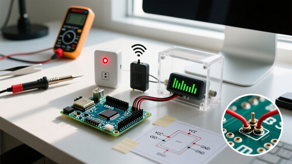
- Bulk Storage: Solder a 470µF to 1000µF electrolytic capacitor across the VCC and GND pins of the audio amplifier. This acts as a local reservoir to supply transient bass spikes.
- High-Frequency Filtering: Place a 0.1µF (100nF) ceramic capacitor in parallel with the electrolytic capacitor. The ceramic cap has a much lower Equivalent Series Resistance (ESR) and will filter out high-frequency switching noise generated by the Class-D amp's internal MOSFETs, preventing it from bleeding back into the Arduino's sensitive ADC circuitry.
Summary Checklist for Clean Audio
Before tearing apart your breadboard in frustration, run through this diagnostic sequence:
- Isolate the Signal: Use an oscilloscope or a multimeter with a frequency counter to verify your PWM or I2S clock signals are actually toggling at the expected pins.
- Check Logic Levels: Ensure no 5V TX lines are directly connected to 3.3V RX pins without a level shifter or series resistor.
- Inspect the SD Card: Reformat to FAT32 with 4096-byte clusters; rename folders to strict two-digit numerals.
- Beef up the Power: Add bulk decoupling capacitors to your audio amplifier stage to prevent brownout resets.
By understanding the physical and electrical realities of microcontroller peripherals, you can reliably play sound from Arduino and elevate your embedded projects from noisy prototypes to polished, production-ready hardware. For advanced multi-channel audio routing, consider migrating to DSP-equipped boards like the Teensy 4.1 or the Arduino Portenta H7, which feature dedicated audio processing pipelines and native I2S/TDM interfaces.