
The Modern Landscape of Arduino Bot Development
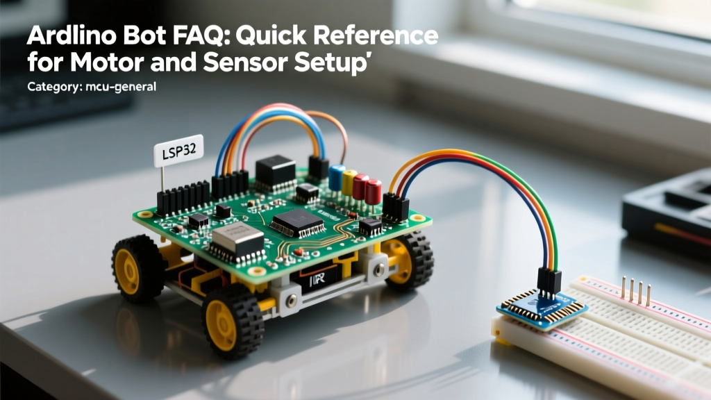
Building a reliable Arduino bot requires bridging the gap between software logic and harsh electrical realities. While the classic ATmega328P remains a staple for beginners, the 2026 robotics landscape heavily favors hybrid architectures, integrating 3.3V high-efficiency microcontrollers with robust 5V or 12V actuator systems. This quick reference FAQ addresses the most common hardware bottlenecks, power routing failures, and sensor integration issues faced by makers today.
Quick Reference: Microcontroller Selection for Bots
| Microcontroller | Logic Level | PWM Channels | Approx. Price | Best Use Case |
|---|---|---|---|---|
| Arduino Uno R3 | 5V | 6 | $15.00 - $27.00 | Simple 2WD obstacle avoidance bots |
| Arduino Uno R4 Minima | 5V (3.3V tolerant) | 6 | $17.50 | Complex kinematics requiring 14-bit DAC |
| ESP32-S3 DevKitC-1 | 3.3V | Up to 14 | $7.00 - $10.00 | ROS-integrated bots, Wi-Fi telemetry |
| Arduino Nano RP2040 | 3.3V | 11 | $22.00 | Machine learning (TinyML) vision bots |
Power and Motor Control FAQ
Why does my Arduino reset every time the motors start moving?
This is the most common failure mode in DIY robotics, caused by Back-EMF (Electromotive Force) and voltage brownouts. DC motors are essentially generators when spinning down or changing direction. They send high-voltage spikes back into your power rail. Furthermore, the inrush current of a stalled or starting DC motor can easily exceed 1.5A, causing a momentary voltage drop (brownout) on the 5V rail that resets the microcontroller.
The Fix:
- Separate Power Domains: Never power motors directly from the Arduino 5V pin. Use a dedicated 2S Li-ion battery pack (e.g., two Molicel P26A 18650 cells in series, providing 7.4V nominal and 25A continuous discharge).
- Decoupling Capacitors: Solder a 100nF ceramic capacitor directly across the motor terminals to absorb high-frequency noise. Add a bulk 470µF electrolytic capacitor across the motor driver's main power input terminals.
- Common Ground: Ensure the Arduino GND, battery GND, and motor driver GND are all tied together at a single star-ground point to prevent ground loops.
L298N vs. TB6612FNG vs. DRV8871: Which motor driver should I use?
The ubiquitous L298N is a legacy bipolar junction transistor (BJT) driver. While cheap ($4-$6), it suffers from a massive voltage drop (1.5V to 2.0V) and poor thermal efficiency, often requiring bulky heatsinks. For modern Arduino bot builds, we strongly recommend MOSFET-based drivers.
According to the Pololu Motor Controllers and Drivers Guide, the TB6612FNG ($3-$5) is the ideal dual-channel replacement. It handles 1.2A continuous current per channel with a voltage drop of only 0.5V, running cool without a heatsink. For heavier bots requiring high-torque 12V gear motors, the DRV8871 (detailed in the Texas Instruments DRV8871 documentation) is a single-channel powerhouse capable of 3.6A continuous current, utilizing PWM current regulation to prevent motor overheating.
Sensor Integration and Logic Level FAQ
How do I safely connect 5V ultrasonic sensors to a 3.3V ESP32-based bot?
Sensors like the HC-SR04 operate at 5V logic and output a 5V echo pulse. Feeding this directly into a 3.3V GPIO pin on an ESP32 or Arduino Nano RP2040 will degrade the silicon over time or instantly fry the pin.
Quick Reference Solutions:
- Voltage Divider (Cheap but slow): Use a 1kΩ and 2kΩ resistor divider on the Echo pin. Warning: Parasitic capacitance can distort high-speed signals.
- Logic Level Shifter (Recommended): Use a bi-directional MOSFET-based logic level converter (like the BSS138 breakout board, ~$1.50). It safely translates 3.3V to 5V and back without signal degradation.
- Upgrade the Sensor: Ditch the HC-SR04 entirely. The VL53L1X Time-of-Flight (ToF) sensor ($12-$15) uses I2C, is inherently 3.3V/5V tolerant, and provides millimeter-accurate distance readings up to 400cm without the acoustic blind spots of ultrasonic modules.
My I2C LiDAR and IMU keep freezing or returning zero. Why?
I2C bus instability is the bane of multi-sensor Arduino bots. If your TFmini-S LiDAR and MPU6050 IMU randomly drop off the bus, you likely have missing or inadequate pull-up resistors. The internal pull-ups on the ATmega328P (approx. 20kΩ to 50kΩ) are far too weak for a bus with multiple modules and long wires.
Pro-Tip: Add external 4.7kΩ pull-up resistors from both the SDA and SCL lines to the logic voltage (3.3V or 5V). If you are running the I2C bus at Fast Mode (400kHz), drop the resistor value to 2.2kΩ to ensure sharp signal rise times.
Software Architecture FAQ
Why is using delay() destroying my bot's navigation?
The delay() function is a blocking command. When your Arduino bot executes delay(500) to wait for an ultrasonic ping, it is entirely deaf and blind to encoder ticks, bump switches, and edge-detection sensors. This leads to bots that crash into walls while 'thinking'.
The Fix: Implement non-blocking code using millis(). By tracking the elapsed time since the last sensor poll, your main loop can run thousands of times per second, continuously checking for hazards while timing your motor maneuvers. As noted in the Arduino Uno R4 Minima Official Documentation, utilizing hardware timers alongside millis() allows for precise PID motor control without blocking the main execution thread.
What is a State Machine and why does my bot need one?
A Finite State Machine (FSM) replaces spaghetti-code if/else ladders with a structured flow. Instead of asking 'what should I do right now?', an FSM asks 'what state am I in, and what conditions trigger a transition?'
Standard Bot States:
- STATE_FORWARD: Both motors at 80% PWM. Transition to STATE_EVADE if front ToF sensor reads < 25cm.
- STATE_EVADE: Stop, reverse 10cm, rotate 90 degrees. Transition to STATE_FORWARD once rotation is complete.
- STATE_PANIC: Triggered by bump switch or cliff sensor. Immediate motor brake and reverse.
Troubleshooting Matrix: Common Arduino Bot Failures
| Symptom | Root Cause | Hardware / Software Fix |
|---|---|---|
| Bot drifts left or right when told to go straight | Manufacturing variance in DC gear motors; PWM mismatch. | Implement a trim variable in code (e.g., Left = PWM * 0.95). For precision, upgrade to motors with magnetic encoders and run a closed-loop PID controller. |
| Motor driver gets too hot to touch | Using an L298N near its 2A limit; poor heat dissipation. | Switch to a TB6612FNG or DRV8871. Ensure the motor stall current does not exceed the driver's peak rating. |
| Ultrasonic sensor returns random 0cm or 400cm values | Acoustic crosstalk; sensor ringing; 5V rail noise. | Wrap the sensor barrel in heat-shrink tubing to narrow the beam. Add a software median filter to discard outlier readings. |
| Code uploads, but bot does nothing | Motor driver logic pins wired to Arduino PWM pins that don't support hardware PWM. | Verify pinout. On Uno R3, pins 3, 5, 6, 9, 10, 11 support PWM. Analog pins (A0-A5) do not. |
Final Takeaways for Reliable Bot Building
A successful Arduino bot is 20% code and 80% electrical engineering. By prioritizing clean power routing, utilizing modern MOSFET motor drivers, and respecting logic level boundaries, you eliminate the vast majority of hardware gremlins. Keep this quick reference handy on your workbench, and always prototype your power distribution on a breadboard before committing to a soldered perfboard or custom PCB.