
Why Your IR Remote Arduino Setup is Failing
Integrating an IR remote Arduino system is often a maker's first foray into wireless communication. It seems simple: wire a receiver, include a library, and read hex codes. However, as many hobbyists and engineers discover, IR setups are notoriously fragile in real-world environments. If your Arduino is returning 0xFFFFFFFF (repeat codes), failing to decode signals entirely, or triggering phantom inputs, you are likely dealing with one of three core failure domains: outdated library APIs, Automatic Gain Control (AGC) saturation, or power rail noise.
This comprehensive troubleshooting guide bypasses generic advice and dives deep into the specific hardware and software edge cases that break IR receiver circuits in 2026, focusing on the ubiquitous VS1838B and the industrial-grade TSOP38238 sensors.
Hardware Matrix: Identifying Your IR Receiver
Before troubleshooting code, you must identify your exact receiver model. The market is flooded with generic sensors that have vastly different electrical characteristics. Using the wrong biasing or expecting industrial performance from a sub-$0.20 clone will lead to endless frustration.
| Specification | Generic VS1838B (Clone) | Vishay TSOP38238 (OEM) | Adafruit 157 (TSOP382) |
|---|---|---|---|
| Typical Cost (2026) | $0.10 - $0.25 (Bulk) | $1.15 - $1.60 | $2.50 (Breakout) |
| Carrier Frequency | 37.9 kHz (Wide tolerance) | 38.0 kHz (Tight bandpass) | 38.0 kHz |
| Supply Voltage | 2.7V to 5.5V | 2.5V to 5.5V | 3.0V to 5.0V |
| AGC & Noise Suppression | Poor (Prone to CFL/LED blinding) | Excellent (Active filtering) | Excellent |
| Output Logic (Idle) | HIGH (Pull-up required) | HIGH (Internal Pull-up) | HIGH |
Expert Insight: If your project is deployed in a room with modern dimmable LED bulbs or large south-facing windows, the generic VS1838B will likely fail due to broadband optical noise. Upgrade to the Vishay TSOP38238 for its superior internal bandpass filter and AGC algorithm.
Failure Mode 1: The IRremote Library API Shift (Software)
The single most common reason an IR remote Arduino sketch fails to compile or decode in modern IDEs is the massive architectural shift in the Arduino-IRremote library between version 2.x and the current v4.x/v5.x releases. Most online tutorials from 2018-2021 use deprecated syntax that silently fails or throws compilation errors on current board packages.
Deprecated vs. Modern Syntax
In older versions, the decode() function required a pointer to a results object, and the hex value was stored directly in results.value. In modern versions, the library manages the results object internally, and data is nested within the decodedIRData struct.
Legacy Code (Fails on v4.x+):
#include <IRremote.h>
int RECV_PIN = 11;
IRrecv irrecv(RECV_PIN);
decode_results results;

void setup() {
  Serial.begin(9600);
  irrecv.enableIRIn();
}
void loop() {
  if (irrecv.decode(&results)) {
    Serial.println(results.value, HEX);
    irrecv.resume();
  }
}
Modern Fix (v4.x / v5.x Compliant):
#include <IRremote.hpp> // Note the .hpp extension
const int RECV_PIN = 11;

void setup() {
  Serial.begin(115200); // Faster baud for modern debugging
  IrReceiver.begin(RECV_PIN, ENABLE_LED_FEEDBACK);
}

void loop() {
  if (IrReceiver.decode()) {
    // Access the nested struct for the actual command data
    Serial.println(IrReceiver.decodedIRData.decodedRawData, HEX);

    // Modern protocol identification
    if (IrReceiver.decodedIRData.protocol == NEC) {
      Serial.println("Detected NEC Protocol");
    }
    IrReceiver.resume();
  }
}
Failure Mode 2: Ambient Light & AGC Saturation
If your Arduino Serial Monitor prints random, erratic hex codes when no remote is pressed, or if it completely ignores your remote control, your receiver's Automatic Gain Control (AGC) is likely saturated. IR receivers amplify microvolt signals from the internal photodiode. When hit with intense ambient infrared radiation (like direct sunlight or the PWM flicker from cheap LED room lights), the internal amplifier maxes out and deafens the sensor to your 38kHz remote.
Diagnostic Steps for Optical Noise
- The Shadow Test: Cup your hand completely over the IR receiver dome to block all ambient light. Press a button on your remote. If the Arduino suddenly decodes the signal perfectly, you have an ambient light saturation issue.
- The Multimeter Test: Set your multimeter to DC Voltage. Probe the Signal (OUT) pin. It should idle at your logic voltage (e.g., 5.0V). If the voltage is fluctuating rapidly between 0V and 5V without a remote present, the sensor is demodulating environmental noise.
Hardware Fixes for AGC Saturation
- Physical Shrouding: Heat-shrink tubing is a maker's best friend. Slide a piece of black, opaque heat-shrink over the sensor, leaving only the very tip of the dome exposed. This narrows the field of view and blocks off-axis light pollution.
- Optical Filters: For advanced builds, place a dark acrylic IR-pass filter (like the Rosco #382 filter) over the receiver to block visible light spectrum interference.
- Carrier Frequency Mismatch: Ensure your remote actually transmits at 38kHz. Some older Sony devices use 40kHz, and certain RC toys use 56kHz. A 38kHz TSOP will heavily attenuate a 40kHz signal, making it highly susceptible to noise dropout.
Failure Mode 3: Power Rail Ripple & Voltage Sag
IR receivers draw highly dynamic current. When a strong IR signal hits the photodiode, the internal amplifier ramps up, causing sudden current spikes. If your Arduino's 5V rail has high impedance or ripple (common when powered via a cheap USB laptop charger or a long, thin USB cable), these spikes cause the VCC pin to momentarily sag. This brownout resets the receiver's internal state machine, resulting in truncated or corrupted hex codes.
The RC Decoupling Fix
To stabilize the power delivery to a generic VS1838B, you must implement a local low-pass RC filter directly at the sensor pins. Do not rely on the Arduino's onboard capacitors; the trace inductance is too high to suppress high-frequency transients.
- Resistor: Solder a 100Ω resistor in series with the VCC line, as close to the receiver's VCC pin as possible.
- Capacitor: Solder a 4.7µF to 10µF ceramic or electrolytic capacitor between the receiver's VCC (after the resistor) and GND pins.
This local energy reservoir supplies the instantaneous current spikes required by the AGC amplifier, completely eliminating phantom decode errors caused by USB power ripple.
Master Diagnostic Flowchart
When facing an unresponsive or erratic IR remote Arduino build, follow this exact sequence to isolate the fault domain:
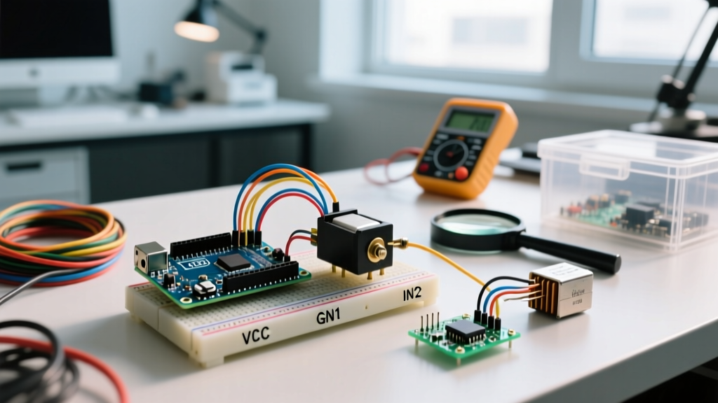
- Verify Wiring Pinout: Looking at the front (mesh/dome side), the pins on most VS1838B sensors are: 1: OUT, 2: GND, 3: VCC. However, always check the specific datasheet, as some Adafruit and Vishay variants swap GND and OUT.
- Run IRrecvDumpV3: Abandon your custom logic. Flash the official
IRrecvDumpV3example sketch from the modern IRremote library. This sketch uses deep decoding and will tell you if the hardware is receiving any pulses at all. - Check the Remote Battery: A dying CR2032 or AAA battery drops the remote's carrier frequency and reduces LED output power. Test with a known-good smartphone camera (point the remote at the camera lens and press a button; you should see a bright purple/white flash on the screen).
- Isolate Power: Disconnect motors, servos, and high-draw LEDs from the Arduino. Power the board via a high-quality 5V/2A wall adapter. If decoding works, your issue is power rail noise, not the IR circuit.
Summary
Troubleshooting an IR remote Arduino interface requires looking past the code and understanding the analog realities of photodiodes, 38kHz carrier waves, and modern library architectures. By updating your syntax to the v4.x IrReceiver API, implementing proper 100Ω/4.7µF power decoupling, and shielding your sensor from broadband LED noise, you can transform a frustrating, unreliable prototype into a robust, production-ready control interface.