
Understanding Piezoelectric Speaker Specifications
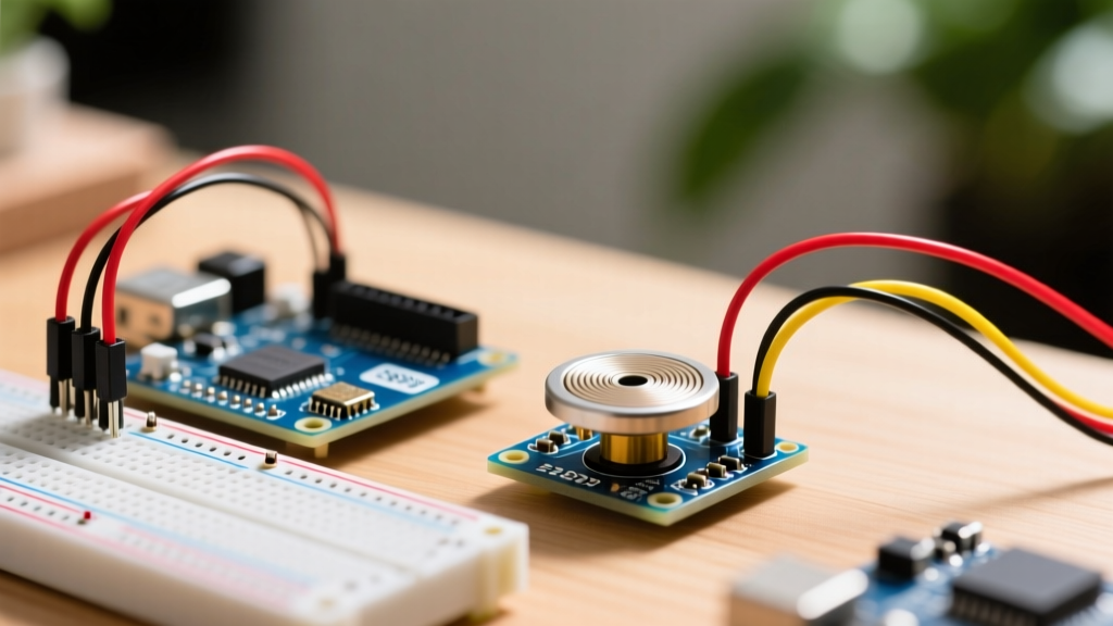
When integrating a piezoelectric speaker Arduino setup, makers often treat the transducer as a simple resistive load like an LED. This is a fundamental error that leads to weak audio output and, in severe cases, destroyed microcontroller GPIO pins. Piezoelectric transducers are inherently capacitive. According to the principles of piezoelectricity, the ceramic element deforms under an applied electric field, but it also stores charge like a capacitor.
Typical bare piezo elements (such as the popular AST1240MLTRQ 12mm transducer or the Murata PKM13EPYH4000-B0) exhibit a capacitance between 1.5nF and 15nF. When you output a 5V square wave via PWM at 4kHz, the rapid voltage transition ($dV/dt$) causes a massive inrush current spike. Without current limiting, this spike can exceed the absolute maximum rating of an ATmega328P GPIO pin (40mA), degrading the silicon over time.
⚠️ Critical Hardware Warning: Never wire a bare piezoelectric element directly between a microcontroller GPIO pin and GND without a series current-limiting resistor. Always use a minimum 100Ω series resistor and a 1MΩ parallel bleeder resistor to discharge the piezo capacitance between pulses.
Microcontroller Board Compatibility Matrix
Not all development boards handle audio generation equally. The compatibility of your piezoelectric speaker Arduino project depends heavily on the MCU's timer architecture, logic voltage, and core library support. Below is a 2026 compatibility matrix for the most common maker boards.
| Development Board | MCU Core | Logic Level | Native tone() Support | PWM / DAC Architecture | Timer Conflict Risk |
|---|---|---|---|---|---|
| Arduino Uno R3 / Nano | ATmega328P | 5V | Yes | 8-bit PWM (Timer1/2) | High (Breaks PWM on Pins 3 & 11) |
| Arduino Mega 2560 | ATmega2560 | 5V | Yes | 8/16-bit PWM | Medium (Uses Timer2) |
| ESP32 DevKit V1 / S3 | Xtensa LX6/LX7 | 3.3V | No (Use ledc) | LEDC Hardware PWM (Up to 16ch) | None (Dedicated LEDC peripheral) |
| Raspberry Pi Pico | RP2040 | 3.3V | Yes (Earlephilhower core) | 16 PWM Slices | Low |
The ESP32 LEDC Workaround
If you are using an ESP32, the standard Arduino tone() function is not natively supported in the Espressif core. Instead, you must use the LED Control (LEDC) peripheral. You will need to configure a channel, set the frequency, and write a 50% duty cycle to achieve the loudest square wave. This actually provides superior compatibility for multi-tone projects, as the ESP32 can drive multiple piezo speakers simultaneously without software timer bottlenecks.
Direct Drive vs. Amplified Drive Circuits
The volume (Sound Pressure Level, or SPL) of your piezoelectric speaker is directly tied to the peak-to-peak voltage ($V_{pp}$) applied across its terminals. A bare element rated for 75dB at 10Vpp will only produce roughly 69dB if driven directly from a 5V Arduino pin. To maximize output, you must choose the correct driver topology.
1. Direct GPIO Drive (Low Cost, Low Volume)
- Use Case: Simple beep notifications, proximity alarms, indoor use.
- Cost: ~$0.15 - $0.30 per unit (bare component).
- Wiring: GPIO → 100Ω Resistor → Piezo (+) | Piezo (-) → GND. Place a 1MΩ resistor in parallel with the piezo.
- Max SPL: 70-80dB @ 10cm.
2. NPN Transistor Switch (Medium Volume)
By using a standard 2N3904 NPN transistor, you can switch a higher voltage rail (e.g., 9V or 12V) using the Arduino's 5V or 3.3V logic. This allows you to drive the piezo closer to its maximum rated voltage.
- Use Case: Outdoor alarms, automotive dash indicators.
- Wiring: GPIO → 1kΩ Base Resistor → 2N3904 Base. Emitter to GND. Collector to Piezo (-). Piezo (+) to 12V rail. Crucial: Add a 1N4148 flyback diode in reverse across the piezo to protect the transistor from back-EMF.
- Max SPL: 85-95dB @ 10cm.
3. H-Bridge Differential Drive (Maximum Volume)
For the absolute maximum SPL without exceeding the piezo's voltage rating, use an H-Bridge motor driver (like the TI DRV8833 or L293D). By driving one side of the piezo high while the other goes low, and then reversing, you effectively double the voltage swing. A 5V supply yields a 10Vpp swing across the piezo, resulting in a +6dB increase in volume compared to single-ended drive. This is the preferred topology for professional IoT alert systems where audio clarity in noisy environments is mandatory.
The Resonance Trap: Matching Frequency to Hardware
The most common reason makers abandon piezo speakers is the "Resonance Trap." Unlike electromagnetic speakers or broadband piezos, standard ceramic piezo transducers are highly resonant devices. The AST1240MLTRQ, for example, has a mechanical resonant frequency of 4.0kHz ± 0.5kHz.
If you use the Adafruit tone tutorial to play a standard 440Hz (A4) musical note, the speaker will output a faint, muffled click. The ceramic element simply cannot move enough air at frequencies far below its mechanical resonance.
Compatibility Solution: If your project requires musical melodies or multi-octave audio, you must purchase a broadband piezo audio transducer (such as the Murata 7BB-20-6L0 paired with a custom Helmholtz cavity) or switch to an electromagnetic buzzer. If you only need alarm tones, use the `tone(pin, 4000)` function to hit the exact resonant peak for maximum efficiency.
Common Failure Modes and Edge Cases
Even with correct wiring, piezoelectric speaker Arduino integrations can fail in subtle ways. Watch out for these specific edge cases:
- Timer Conflicts on ATmega328P: The Arduino `tone()` library monopolizes Timer2. If your project also uses `analogWrite()` on Pin 3 or Pin 11, or relies on the IRremote library (which also uses Timer2), your audio and PWM outputs will conflict and fail. Fix: Use the `toneAC` library or shift to hardware PWM.
- Ceramic Depolarization: Applying DC voltage continuously (e.g., `digitalWrite(pin, HIGH)` without toggling) will permanently depolarize the PZT ceramic, ruining the speaker. Always use AC-coupled signals (PWM/Square waves).
- Acoustic Short-Circuiting: If you mount a bare piezo disc over a hole in an enclosure without sealing the edges with RTV silicone, the front and back sound waves will cancel each other out (acoustic short circuit), resulting in near-zero volume.
Frequently Asked Questions
Can I use a passive piezo buzzer module with a 3.3V ESP32?
Yes, but many cheap "active/passive" modules sold online include a built-in NPN transistor and a pull-up resistor designed for 5V. If you feed the signal pin 3.3V, the transistor may not fully saturate, resulting in weak output. Always check the module schematic; if it has an onboard transistor, drive the signal pin with a logic-level MOSFET or use a bare piezo element wired directly to the ESP32 GPIO with a series resistor.
Why does my piezo speaker click when the Arduino boots up?
During boot, ATmega and ESP32 GPIO pins float before the bootloader initializes them. This floating state can induce random voltage spikes across the piezo's capacitance. Fix this by adding a 10kΩ pull-down resistor between the GPIO pin and GND to hold the line low during initialization.
What is the maximum wire length between the Arduino and the piezo?
Because piezos are high-impedance, capacitive loads, long wires act as antennas and add parasitic capacitance. Keep wire runs under 30cm (12 inches). For longer runs, place the driver transistor or H-bridge within 5cm of the piezo speaker, and run the low-current logic signal from the Arduino over the longer distance.