
The Foundation of Microcontroller Configuration
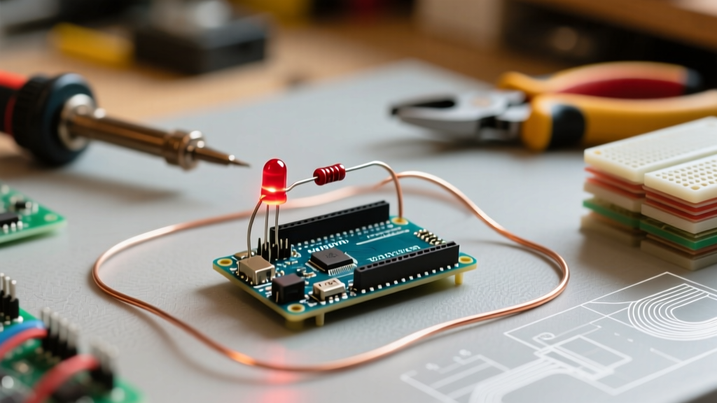
Learning how to properly configure an arduino blink an led circuit is the foundational rite of passage for every embedded systems engineer and maker. While often dismissed as a trivial 'Hello World' exercise, correctly configuring this circuit requires a precise understanding of hardware physics, GPIO current limitations, IDE board mapping, and non-blocking software architecture. In 2026, with the widespread adoption of the Arduino Uno R4 Minima and the Nano ESP32 alongside legacy ATmega328P boards, the configuration parameters have shifted significantly. Legacy tutorials that blindly recommend 220-ohm resistors and blocking delay functions are no longer sufficient—and can actually damage modern microcontroller pins.
This comprehensive configuration guide will walk you through the exact hardware calculations, IDE environment setup, and professional-grade C++ firmware required to safely and efficiently blink an LED on modern Arduino architectures.
Hardware Configuration: Sizing the Current-Limiting Resistor
The most common failure mode in beginner circuits is driving an LED directly from a GPIO pin without a current-limiting resistor, or using an incorrectly sized resistor that exceeds the microcontroller's absolute maximum ratings. To properly configure the hardware, we must apply Ohm's Law, a fundamental principle detailed in resources like All About Circuits.
The formula for the resistor is: R = (V_source - V_forward) / I_target.
The 8mA vs. 20mA Paradigm Shift
For over a decade, the Arduino Uno R3 (based on the Microchip ATmega328P) dictated the standard configuration. The ATmega328P can safely source up to 20mA per GPIO pin, making a standard 220Ω resistor perfectly safe for a 5V logic system driving a red LED (V_f ≈ 2.0V). However, the modern Arduino Uno R4 Minima utilizes the Renesas RA4M1 ARM Cortex-M4 processor. According to the RA4M1 datasheet, the absolute maximum current per I/O pin is strictly limited to 8mA. Pushing 13mA through a 220Ω resistor on an Uno R4 will degrade the silicon over time and cause thermal throttling or permanent pin failure.
Resistor Configuration Matrix
Use the following matrix to select the correct through-hole resistor (1/4W tolerance) based on your specific board and LED color. Data sourced from standard diode characteristics outlined in SparkFun's LED Tutorial.
| LED Color | Forward Voltage (V_f) | Target Current | Resistor for Uno R3 (5V Logic, 20mA max) | Resistor for Uno R4 / Nano ESP32 (8mA max) |
|---|---|---|---|---|
| Red | 2.0V | 10mA - 15mA | 220Ω | 330Ω to 470Ω |
| Yellow / Green | 2.2V | 10mA - 15mA | 220Ω | 330Ω to 470Ω |
| Blue / White | 3.2V | 10mA - 15mA | 100Ω to 150Ω | 220Ω to 330Ω |
Pro-Tip: Modern high-efficiency LEDs (like the Kingbright WP7113 series) produce over 1500 mcd at just 5mA. There is rarely a need to drive indicator LEDs at 20mA in 2026. Configuring your circuit for 5mA-10mA extends component lifespan and reduces thermal load on the MCU.
IDE Configuration: Board Cores and Port Mapping
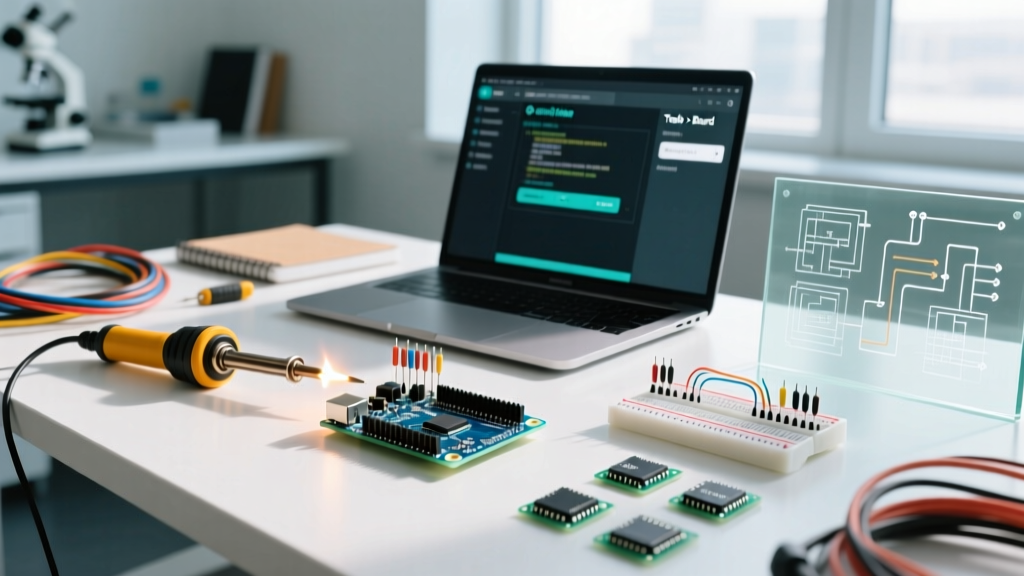
Hardware is only half the battle. The Arduino IDE 2.3.x environment requires precise board core configuration to compile and upload the firmware correctly. A frequent edge case occurs when users plug in an Uno R4 Minima but leave the IDE configured for the legacy 'Arduino Uno', resulting in architecture mismatch errors during compilation.
- Install the Correct Core: Open the Boards Manager (Ctrl+Shift+B or Cmd+Shift+B). Search for
Arduino Renesas ra4m1and install the latest version. For Nano ESP32 users, install theArduino ESP32 Boardscore. - Verify the Port Mapping: Navigate to Tools > Port. On Windows 11, genuine Arduinos will enumerate as a standard COM port (e.g., COM3). If you are using a budget-friendly Nano V3.0 clone (typically priced around $4.50 compared to the $21.50 genuine Nano ESP32), it likely uses the CH340 USB-to-Serial chip. You must download and install the official WCH CH340 drivers, or the port will not appear in the IDE dropdown.
- Programmer Selection: For standard bootloader uploads via USB, ensure Tools > Programmer is set to 'AVRISP mkII' (for R3) or simply rely on the default serial upload mechanism for ARM/ESP32 boards. Do not select 'USBasp' unless you are actively burning a new bootloader via ICSP headers.
Software Configuration: Blocking vs. Non-Blocking Timers
The default 'Blink' sketch provided in the Arduino IDE examples uses the delay() function. While functional for a single task, delay() is a blocking function that halts the CPU, preventing the microcontroller from reading sensors, handling interrupts, or managing wireless communications. Professional firmware configuration requires a non-blocking state machine using the millis() timer.
The Professional millis() Configuration
The following code configures a non-blocking blink routine. This allows the MCU to execute thousands of background loop iterations per second while toggling the LED precisely every 1000 milliseconds. Further IDE configurations and best practices can be found in the Arduino IDE 2 Documentation.
// Configuration: Non-Blocking LED Blink
const int ledPin = 13;         // Hardware pin mapping
unsigned long previousMillis = 0; // Stores last toggle time
const long interval = 1000;    // Toggle interval in milliseconds
int ledState = LOW;            // Current GPIO state

void setup() {
  // Configure the digital pin as an output
  pinMode(ledPin, OUTPUT);

  // Optional: Configure serial for debugging state changes
  Serial.begin(115200);
  while (!Serial) { ; } // Wait for serial port to connect (Native USB boards)
}

void loop() {
  // Read the current uptime in milliseconds
  unsigned long currentMillis = millis();

  // Check if the interval has passed (handles 50-day rollover safely)
  if (currentMillis - previousMillis >= interval) {
    // Save the last time the LED was toggled
    previousMillis = currentMillis;

    // Toggle the state using a ternary operator
    ledState = (ledState == LOW) ? HIGH : LOW;

    // Apply the configured state to the hardware pin
    digitalWrite(ledPin, ledState);
  }

  // The CPU is free to execute other tasks here
  // e.g., readSensors(), handleWiFi(), processUART()
}
Diagnostic Troubleshooting Matrix
When your configuration fails to produce a blinking LED, use this diagnostic matrix to isolate the fault domain. Troubleshooting requires a systematic elimination of hardware, driver, and software variables.
| Observed Symptom | Probable Root Cause | Configuration Fix & Verification |
|---|---|---|
| Upload succeeds, but LED stays off. | Incorrect board selected in IDE; firmware compiled for wrong memory map. | Verify Tools > Board matches exact hardware. Re-compile and upload. |
| LED glows extremely dimly. | Resistor value too high, or pin configured as INPUT instead of OUTPUT. | Check code for pinMode(pin, OUTPUT). Measure resistor with a multimeter. |
| IDE throws 'Port not found' error. | Missing CH340/CP2102 drivers for clone boards, or faulty USB data cable. | Test with a known 'data-sync' USB cable (not a charge-only cable). Install WCH drivers. |
| LED blinks erratically or freezes. | Memory overflow or blocking code causing watchdog timer resets. | Ensure no infinite while() loops exist without yield conditions. Check SRAM usage. |
| Pin 13 blinks, but external LED on Pin 8 does not. | Missing common ground between external breadboard and Arduino GND pin. | Connect Arduino GND to the breadboard's negative rail to complete the circuit. |
Summary and Next Steps
Configuring an arduino blink an led circuit is far more than a simple wiring exercise; it is a strict test of your understanding of microcontroller architecture, electrical limits, and asynchronous programming. By respecting the 8mA GPIO limits of modern ARM-based boards like the Uno R4 Minima, selecting precise current-limiting resistors, and implementing non-blocking millis() timers, you establish a robust foundation for complex IoT and robotics projects. Once this baseline configuration is verified, you can confidently expand your circuit to include PWM dimming via analogWrite(), integrate I2C OLED displays, or implement deep-sleep routines for battery-powered sensor nodes.