
The 5V Logic Problem: Why Your Arduino Needs a MOSFET
Microcontrollers like the ATmega328P found in the classic Arduino Uno, or the Renesas RA4M1 in the modern Arduino Uno R4 Minima, are brilliant for logic processing but severely limited in power delivery. A standard Arduino GPIO pin can safely source or sink a maximum of 20mA (with an absolute ceiling of 40mA before risking permanent silicon damage). Furthermore, the output voltage is capped at the board's logic level—typically 5V or 3.3V.
If you want to control a 12V LED strip drawing 3 Amps, a DC water pump, or a high-power heating element, connecting it directly to the microcontroller will instantly destroy the MCU. To bridge the gap between low-power logic and high-power loads, we use a Power MOSFET (Metal-Oxide-Semiconductor Field-Effect Transistor) as a solid-state switch. However, selecting and wiring the correct MOSFET Arduino combination requires an understanding of gate thresholds, thermal dissipation, and inductive kickback.
The IRF520 Trap: Standard vs. Logic-Level MOSFETs
Walk into any electronics store or browse online marketplaces, and you will find the IRF520 MOSFET driver module marketed heavily for Arduino projects. Priced around $1.50, it seems like the perfect solution. Unfortunately, for 5V microcontrollers, the IRF520 is a notorious trap.
The IRF520 is a standard-level MOSFET. While its datasheet lists a Gate Threshold Voltage (Vgs(th)) of 2.0V to 4.0V, this only indicates the voltage required to let a microscopic 250µA of current pass. To fully turn the MOSFET on and achieve a low Drain-Source On-Resistance (Rds(on)), a standard MOSFET requires 10V on the gate. When driven by a 5V Arduino pin, the IRF520 operates in its linear (ohmic) region. It acts like a high-value resistor, dropping significant voltage across the junction and generating massive amounts of heat, often leading to thermal runaway and load failure.
For a 5V or 3.3V Arduino, you must use a Logic-Level MOSFET, indicated by an "L" in the part number (e.g., IRLZ44N, IRLB8721). These are specifically engineered to achieve minimal Rds(on) at Vgs = 4.5V or lower.
Component Comparison Matrix
| Parameter | IRF520 (Standard) | IRLZ44N (Logic-Level) | IRLB8721 (High-Performance) |
|---|---|---|---|
| Vgs(th) Range | 2.0V - 4.0V | 1.0V - 2.0V | 1.3V - 2.3V |
| Rds(on) @ Vgs = 5V | ~0.40Ω (Not fully on) | 0.022Ω | 0.0045Ω |
| Max Continuous Drain Current (Id) | 9.2A | 47A | 62A |
| Typical Unit Cost (2026) | $1.20 - $1.50 | $1.80 - $2.50 | $2.50 - $3.20 |
| Suitability for 5V Arduino | Poor (High Heat) | Excellent | Superior (Low PWM Loss) |
Step-by-Step Wiring Guide for High-Current Loads
Wiring a MOSFET seems straightforward—Gate to Arduino, Drain to Load, Source to Ground. However, omitting passive protection components is the leading cause of MCU resets and blown gates. Follow this precise topology for robust operation.
1. The Gate Resistor (Protecting the MCU)
A MOSFET gate behaves like a small capacitor (often between 1000pF and 3000pF). When the Arduino pin goes HIGH, it attempts to charge this capacitor instantly. This inrush current can exceed the 20mA safe limit of the GPIO pin, degrading the microcontroller over time. Place a 150Ω to 220Ω resistor in series between the Arduino PWM pin and the MOSFET Gate. This limits the charging current while still allowing the gate to charge fast enough for standard PWM frequencies (490Hz or 980Hz).
2. The Pull-Down Resistor (Preventing Boot Glitches)
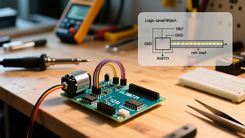
When an Arduino powers on or resets, its GPIO pins float in a high-impedance state before the bootloader finishes and the sketch initializes. If the MOSFET gate is floating, ambient electromagnetic interference (EMI) can capacitively couple onto the gate, partially turning the MOSFET on and activating your high-power load unpredictably. Solder a 10kΩ pull-down resistor directly between the Gate and Source (Ground) to ensure the MOSFET remains firmly off until the MCU explicitly drives the pin HIGH.
3. Flyback Diodes for Inductive Loads
If your load is inductive (DC motors, solenoids, relays, or water pumps), you must account for back-electromotive force (back-EMF). When the MOSFET switches off, the collapsing magnetic field in the motor induces a massive reverse voltage spike that can easily exceed the MOSFET's breakdown voltage (Vdss), punching through the silicon. Wire a flyback diode (such as a 1N4007 for low-frequency switching or a 1N5819 Schottky for high-frequency PWM) in reverse bias across the load terminals (Cathode to V+, Anode to the MOSFET Drain).
Writing the Arduino Sketch
Because logic-level MOSFETs switch incredibly fast, we can use Pulse Width Modulation (PWM) to dim LEDs or control motor speed. The Arduino analogWrite() function handles the hardware timer configuration automatically.
// MOSFET Arduino PWM Control Sketch
const int GATE_PIN = 9; // Pin 9 supports PWM on Uno/Nano

void setup() {
  pinMode(GATE_PIN, OUTPUT);
  digitalWrite(GATE_PIN, LOW); // Ensure off state immediately
}

void loop() {
  // Fade in: 0 to 255 duty cycle
  for (int dutyCycle = 0; dutyCycle <= 255; dutyCycle += 5) {
    analogWrite(GATE_PIN, dutyCycle);
    delay(30);
  }

  // Hold at 50% power for 2 seconds
  analogWrite(GATE_PIN, 127);
  delay(2000);

  // Fade out
  for (int dutyCycle = 255; dutyCycle >= 0; dutyCycle -= 5) {
    analogWrite(GATE_PIN, dutyCycle);
    delay(30);
  }

  delay(1000); // Off for 1 second
}
Thermal Calculations and Heat Sink Sizing
Even logic-level MOSFETs generate heat. Understanding Power MOSFET operating principles and thermal resistance is critical for high-current applications. Let's calculate the thermal requirements for an IRLZ44N switching a 12V, 10A LED array.
- Current (I): 10 Amps
- Rds(on) @ Vgs=5V: 0.022Ω
- Power Dissipation (P = I² × R): 10² × 0.022 = 2.2 Watts
A standard TO-220 package without a heat sink has a Junction-to-Ambient thermal resistance (RθJA) of roughly 62°C/W. A 2.2W dissipation will cause the silicon junction temperature to rise by 136°C above ambient room temperature (25°C + 136°C = 161°C). This exceeds the typical 175°C maximum junction temperature and will trigger thermal shutdown or failure.
The Fix: Attach a small extruded aluminum heat sink with a thermal resistance of ~15°C/W. Using thermal paste, the new temperature rise is 2.2W × 15°C/W = 33°C. The junction will operate at a safe 58°C. For currents above 15A, consider moving to a surface-mount D2PAK package soldered to a copper pour, or use a dedicated motor driver IC.
Troubleshooting Common MOSFET Arduino Failures
Expert Troubleshooting Tip: If your Arduino randomly resets or the onboard voltage regulator gets scorching hot the moment your motor starts, you are experiencing a ground bounce or voltage sag. Never share the same long ground wire between your high-current motor and the Arduino's logic ground. Use a "Star Ground" topology where the power supply ground, motor ground, and Arduino ground all meet at a single, thick terminal block.
Edge Case: High-Frequency PWM Gate Ringing
If you alter the Arduino's hardware timers to output PWM at 20kHz or higher (common for ultrasonic motor control to avoid audible whine), the 220Ω gate resistor will charge the gate too slowly. The MOSFET will spend too much time in the linear region during the transition, leading to catastrophic overheating even at low currents. For frequencies above 5kHz, reduce the gate resistor to 47Ω or, ideally, introduce a dedicated gate driver IC like the TC4427 between the Arduino and the MOSFET to provide the 2A+ peak current required to snap the gate open and closed instantly.
Edge Case: 3.3V Microcontrollers (ESP32 / Arduino Nano 33 IoT)
If you are migrating from a 5V Uno to a 3.3V board like the ESP32 or Arduino Nano 33 IoT, the IRLZ44N might not fully saturate, as its Rds(on) curve flattens out around 4.5V. For 3.3V logic, you must select ultra-low threshold MOSFETs such as the SI2302 (for low currents under 2A) or the CSD17571Q5A for higher power applications, ensuring the datasheet specifies Rds(on) testing at Vgs = 2.5V.