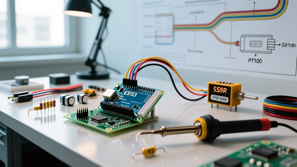

Why Upgrade from Bang-Bang to PID Arduino Control?
When designing a custom reflow oven, sous-vide water bath, or 3D printer hotend, most beginners start with simple bang-bang (hysteresis) control. You set a target temperature, turn the heater on when the reading drops below the threshold, and turn it off when it exceeds it. However, because thermal systems possess inherent mass and latency, bang-bang control inevitably results in aggressive temperature overshoot and continuous oscillation.
Implementing a PID Arduino (Proportional-Integral-Derivative) closed-loop algorithm solves this. By calculating the error rate and accumulated historical error, a PID controller modulates the power output smoothly, achieving a stable setpoint with an accuracy of ±0.5°C or better. In this comprehensive tutorial, we will build a robust AC-powered temperature control system and walk through the industry-standard Ziegler-Nichols tuning method to eliminate guesswork.
2026 Hardware Bill of Materials & Wiring Architecture
To achieve industrial-grade stability, we must avoid cheap thermistors and opt for a Platinum Resistance Temperature Detector (PT100). Below is the recommended hardware stack, reflecting current 2026 maker-market pricing.
| Component | Model / Specification | Est. Cost | Purpose |
|---|---|---|---|
| Microcontroller | Arduino Uno R4 WiFi | $27.50 | Core logic, SPI communication, and PID computation. |
| RTD Amplifier | Adafruit MAX31865 Breakout | $19.95 | Converts PT100 resistance to digital SPI data. |
| Temperature Probe | 3-Wire PT100 RTD (Class A) | $14.00 | High-accuracy temperature sensing up to 400°C. |
| Solid State Relay | Fotek SSR-25DA (AC Zero-Cross) | $9.50 | Switches AC load without mechanical contact wear. |
| Heating Element | 500W AC Cartridge Heater | $12.00 | Thermal output for the controlled environment. |
Wiring Note: Always use a 3-wire PT100 configuration with the MAX31865. As detailed in the Adafruit MAX31865 RTD Guide, a 3-wire setup allows the amplifier to mathematically cancel out the resistance of the copper lead wires, which would otherwise introduce a 2°C to 4°C error in long cable runs.
The AC SSR Bottleneck: Time-Proportional Control
A critical mistake many makers make when building a PID Arduino project is attempting to use the analogWrite() PWM function to drive an AC Solid State Relay. Standard Arduino PWM operates at roughly 490Hz. However, AC zero-crossing SSRs like the SSR-25DA are designed to switch only when the AC sine wave crosses zero volts. Feeding a 490Hz PWM signal into a zero-cross SSR will cause erratic firing, massive electromagnetic interference (EMI), and eventual destruction of the TRIAC.
The solution is Time-Proportional Control. Instead of rapidly pulsing the pin, we define a 'Window Size' (e.g., 2000 milliseconds). If the PID output demands 25% power, the Arduino sets the SSR control pin HIGH for 500ms, then LOW for 1500ms. This slow-cycling method works perfectly with AC zero-cross SSRs and is brilliantly explained in Brett Beauregard's Improving the Beginner's PID series, which forms the foundation of the standard Arduino PID_v1 library.
Executing the Ziegler-Nichols Tuning Method
Guessing Kp, Ki, and Kd values will lead to hours of frustration. Instead, we use the Ziegler-Nichols closed-loop method to mathematically derive the optimal tuning parameters. According to standard Ziegler-Nichols control theory, follow these exact steps:
- Disable Integral and Derivative: In your Arduino code, set
Ki = 0andKd = 0. Set an initialKpvalue of 50. - Induce Oscillation: Set your target temperature to a safe mid-range value (e.g., 100°C). Slowly increase the
Kpvalue in increments of 10 while monitoring the serial plotter. - Find the Ultimate Gain (Ku): Stop increasing Kp the moment the temperature graph begins to oscillate in a continuous, uniform sine wave. The Kp value at this exact threshold is your Ultimate Gain (Ku).
- Measure the Ultimate Period (Tu): Look at the serial plotter and measure the time (in seconds) between two consecutive peaks of the oscillation. This is your Ultimate Period (Tu).
- Calculate Final Parameters: Use the matrix below to calculate your final PID variables.
Ziegler-Nichols Tuning Matrix
| Control Type | Proportional (Kp) | Integral (Ki) | Derivative (Kd) |
|---|---|---|---|
| P Only | 0.5 × Ku | 0 | 0 |
| PI | 0.45 × Ku | 1.2 × Kp / Tu | 0 |
| PID (Full) | 0.6 × Ku | 2.0 × Kp / Tu | Kp × Tu / 8 |
Pro-Tip: For temperature systems, which naturally suffer from thermal lag, a PI or slightly detuned PID configuration is usually superior. Full PID can sometimes overreact to sensor noise.
Real-World Failure Modes & Edge Cases
Even with perfect math, physical hardware introduces edge cases that can ruin your PID Arduino controller. Watch out for these specific failure modes:
1. Electromagnetic Interference (EMI) on the PT100
PT100 sensors measure tiny resistance changes (0.385 ohms per °C). When your 500W AC heater switches on, it generates massive EMI. If your PT100 wires run parallel to your AC load wires, the Arduino will read 'spikes' of 50°C or more, causing the derivative term to panic and shut off the heater. The Fix: Use shielded twisted pair (STP) cable for the RTD, ground the shield at the MAX31865 end only, and physically route the sensor wires at least 4 inches away from AC mains wiring.
2. Integral Windup During Startup
When you first power on a cold oven, the error (Setpoint - Input) is massive. The Integral term accumulates this error rapidly. By the time the temperature reaches the setpoint, the accumulated 'I' term is so large that the heater stays at 100% power, causing severe overshoot. The Fix: The PID_v1 library includes basic anti-windup, but you should manually clamp the Integral term in your code or use the SetOutputLimits() function to restrict the maximum output during the first 60 seconds of operation.
3. SSR Thermal Throttling and Runaway
A generic SSR-25DA drops approximately 1.2V across its internal TRIAC. If your 500W heater draws roughly 4.5 Amps at 110V, the SSR dissipates about 5.4 Watts of heat continuously. Without an adequate heatsink, the SSR's internal temperature will exceed 70°C within minutes, triggering its internal thermal protection and shutting off the heater unexpectedly. The Fix: Always mount AC SSRs to an extruded aluminum heatsink using thermal paste, and ensure the enclosure has passive ventilation slots.
Conclusion
Building a reliable PID Arduino temperature controller requires moving beyond basic code examples and understanding the physical realities of AC switching and thermal mass. By utilizing a MAX31865 RTD amplifier, implementing time-proportional logic for your SSR, and rigorously applying the Ziegler-Nichols tuning method, you will achieve industrial-grade thermal stability for any maker project.