
Understanding Tilt Switch Mechanics for Microcontrollers
When designing orientation-aware electronics, makers and engineers generally choose between multi-axis MEMS accelerometers (like the MPU6050) and simple mechanical tilt switches. While MEMS sensors provide precise vector data, they draw continuous current and require complex I2C/SPI library configurations. For binary applications—such as anti-theft alarms, screen rotation triggers, or safety cut-offs—a tilt switch Arduino configuration remains the most cost-effective and power-efficient solution in 2026.
Modern tilt switches are entirely mercury-free to comply with global RoHS directives. Instead, they utilize a rolling conductive mass (usually a gold-plated steel ball) that bridges two internal electrodes when the sensor is angled past a specific threshold. A standard SW-200D sensor costs roughly $0.15 to $0.30 per unit in bulk, making it ideal for disposable or high-volume consumer IoT devices.
Sensor Selection: SW-200D vs. SW-460D vs. SW-520D
Before wiring your breadboard, you must select the correct mechanical profile for your enclosure. Different models offer varying sensitivity and activation angles.
| Model | Activation Angle | Sensitivity | Best Use Case |
|---|---|---|---|
| SW-200D | ~20° to 45° | High | General tilt detection, anti-theft alarms |
| SW-460D | ~45° to 60° | Medium | Screen rotation, vending machine tilt |
| SW-520D | Directional | Low (Specific Axis) | Directional leveling, specific axis triggers |
Hardware Wiring: Pull-Up vs. Pull-Down Configurations
A tilt switch is essentially a single-pole, single-throw (SPST) mechanical switch. It has only two pins and no polarity. However, connecting one pin directly to a microcontroller digital input without a reference voltage will result in a floating pin. A floating pin acts as an antenna, picking up electromagnetic interference (EMI) and causing erratic state changes.
To stabilize the signal, you must configure a pull-up or pull-down resistor. According to SparkFun's engineering tutorials on pull-up resistors, using the microcontroller's internal pull-up resistor is the most efficient method, as it eliminates the need for external components on the breadboard.
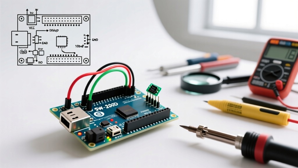
Wiring the SW-200D with Internal Pull-Up
- Pin 1: Connect to Arduino Digital Pin 2 (or any standard GPIO).
- Pin 2: Connect directly to Arduino GND.
In this configuration, when the switch is open (upright), the internal resistor pulls the pin HIGH (5V or 3.3V). When the switch tilts and the ball bridges the contacts, it shorts the pin to GND, pulling it LOW. This means the logic is inverted: LOW equals tilted, HIGH equals upright.
Solving the Mechanical Bounce Issue
The most common failure mode in tilt switch Arduino projects is 'contact bounce.' When the internal steel ball rolls and hits the electrodes, it physically bounces for 5 to 20 milliseconds before settling. To an Arduino running at 16MHz, this single physical tilt registers as dozens of rapid HIGH/LOW transitions, potentially triggering multiple interrupts or corrupting state machines.
Hardware Debounce: The RC Low-Pass Filter
If you are operating in a high-vibration environment where software debounce might miss rapid legitimate state changes, implement a hardware RC filter. By placing a 10kΩ external pull-up resistor and a 0.1µF ceramic capacitor (X7R dielectric) in parallel with the switch, you create a low-pass filter.
Engineering Note: The time constant (τ) of this RC circuit is calculated as τ = R × C. With 10,000 ohms and 0.0000001 farads, τ = 1 millisecond. It takes approximately 5τ (5ms) for the capacitor to discharge enough to register a solid LOW state, effectively masking the micro-bounces of the steel ball.
Core Arduino Sketch: Polling with Software Debounce
For most standard applications, software debouncing is preferred as it saves component costs. The following C++ configuration uses the millis() function to ignore state changes that occur within a 50-millisecond window. This non-blocking approach ensures your main loop remains free to handle other tasks like driving displays or reading sensors.
const int tiltPin = 2;
int tiltState = HIGH;         // Current state
int lastTiltState = HIGH;     // Previous state
unsigned long lastDebounceTime = 0;
unsigned long debounceDelay = 50; // 50ms debounce window

void setup() {
  Serial.begin(115200);
  // Configure internal pull-up resistor
  pinMode(tiltPin, INPUT_PULLUP);
  Serial.println("Tilt Switch Configuration Initialized.");
}

void loop() {
  int reading = digitalRead(tiltPin);

  // Check if state changed, reset debounce timer
  if (reading != lastTiltState) {
    lastDebounceTime = millis();
  }

  // If state has been stable longer than debounceDelay
  if ((millis() - lastDebounceTime) > debounceDelay) {
    if (reading != tiltState) {
      tiltState = reading;

      // Logic is inverted due to INPUT_PULLUP
      if (tiltState == LOW) {
        Serial.println("ALERT: Device Tilted!");
      } else {
        Serial.println("STATUS: Device Upright.");
      }
    }
  }
  lastTiltState = reading;
}
Advanced Configuration: Interrupt-Driven Tilt Detection
If your project is a battery-powered IoT node (e.g., an ESP32 or ATmega328P running on a LiPo cell), polling the pin in the loop() wastes milliamps of current. Instead, configure the tilt switch to trigger a hardware interrupt, allowing the MCU to sleep deeply and wake only when tilted.
According to the official Arduino attachInterrupt() documentation, the Uno and Nano support hardware interrupts only on Digital Pins 2 and 3. The INPUT_PULLUP tutorial on Arduino.cc also confirms that internal pull-ups remain active during most sleep modes, making this configuration ideal for wake-on-tilt circuits.
volatile bool tiltTriggered = false;
const int interruptPin = 2;

void setup() {
  pinMode(interruptPin, INPUT_PULLUP);
  // Trigger on FALLING edge (when ball bridges to GND)
  attachInterrupt(digitalPinToInterrupt(interruptPin), tiltISR, FALLING);
  // Initialize sleep mode configurations here (e.g., LowPower library)
}

void tiltISR() {
  // Keep ISR minimal; set a flag and handle logic in loop
  tiltTriggered = true;
}

void loop() {
  if (tiltTriggered) {
    tiltTriggered = false;
    // Execute wake-up tasks, transmit LoRa/WiFi alert, then return to sleep
  }
}
Troubleshooting and Edge Cases
Even with proper wiring, mechanical tilt switches present unique physical challenges in the field. Use this diagnostic matrix to resolve common configuration issues.
| Symptom | Root Cause | Engineering Solution |
|---|---|---|
| False triggers from motor vibration | High-frequency chassis vibration causes the ball to chatter momentarily. | Increase software debounceDelay to 150ms, or encase the sensor in a silicone dampening sleeve. |
| Fails to trigger on slow tilts | Oxidation on the internal ball or contacts causing high resistance. | Replace the sensor. SW-200D units with gold-plated internals resist oxidation better than cheap nickel variants. |
| Interrupt fires continuously | Missing pull-up resistor, causing the floating pin to oscillate wildly from EMI. | Verify INPUT_PULLUP is defined in setup(), or add an external 10kΩ resistor to 3.3V/5V. |
| Wakes up from sleep instantly | Interrupt trigger edge set incorrectly, or switch is currently closed (tilted) during sleep entry. | Ensure the device is upright before entering sleep, or use CHANGE edge detection with state validation. |
Final Calibration Tips
When mounting the SW-200D to your PCB or enclosure, the orientation of the sensor's flat edge dictates the axis of sensitivity. For X-axis tilt detection, mount the sensor so the internal cavity aligns perpendicular to the X-plane. If you require omnidirectional tilt detection (e.g., a dome alarm that triggers if pushed from any side), mount the sensor vertically, standing on its leads, allowing the ball to roll away from the bottom contacts regardless of the lateral push direction.