
Why Choose a Phototransistor Over an LDR?
When designing light-sensing circuits for microcontrollers, the photoresistor (LDR) is often the default choice due to its simplicity. However, for applications requiring rapid response times, specific spectral sensitivities, or higher linearity, the Arduino phototransistor setup is vastly superior. While an LDR might take 20-50 milliseconds to react to a change in illumination, a silicon NPN phototransistor like the Vishay BPW85B or the TEPT5600 responds in microseconds. This speed is critical for tachometers, optical encoders, and high-speed data reception from IR sources.
Furthermore, phototransistors offer a more predictable transfer function between incident irradiance (mW/cm²) and collector current (mA), making them far easier to calibrate for absolute lux measurements compared to the highly non-linear resistance curve of cadmium sulfide (CdS) photoresistors.
Component Selection: Matching the Sensor to the Spectrum
Not all phototransistors are identical. The silicon junction's physical properties dictate its peak sensitivity wavelength. Selecting the wrong sensor for your ambient light environment will result in poor signal-to-noise ratios.
| Model Number | Peak Wavelength | Best Application | Viewing Angle | Approx. Price (2026) |
|---|---|---|---|---|
| TEPT5600 | 570 nm (Green/Yellow) | Visible light, ambient lux sensing, matching human eye response | ±60° | $0.85 |
| BPW85B | 900 nm (Near-Infrared) | IR remote detection, optical isolation, object counting | ±50° | $0.45 |
| L-53P3C | 940 nm (Infrared) | Line-following robots, reflective object sensors | ±20° | $0.30 |
For general-purpose ambient light sensing (e.g., automatic display dimming or smart home lighting triggers), the TEPT5600 is the optimal choice because its spectral response closely mimics the human eye's photopic vision curve.
Hardware Design: The Emitter-Follower Configuration
To interface a phototransistor with an Arduino's 10-bit ADC (Analog-to-Digital Converter), we must convert the light-induced current into a measurable voltage. The most reliable and common topology is the common-collector (emitter-follower) circuit with a pull-down resistor.
Sizing the Pull-Down Resistor
The value of the pull-down resistor (connected between the emitter and ground) dictates your circuit's sensitivity and saturation point. Ohm's Law (V = I × R) governs this relationship:
- High Resistance (100kΩ - 470kΩ): Extremely sensitive. Ideal for dark environments or detecting distant, low-intensity light sources. Will saturate (read 1023) quickly in direct sunlight.
- Medium Resistance (10kΩ - 47kΩ): The sweet spot for typical indoor ambient lighting (100 to 500 lux). Yields a usable voltage swing between 0.5V and 4.0V.
- Low Resistance (1kΩ - 4.7kΩ): Low sensitivity. Required for outdoor applications or direct sunlight (10,000+ lux) to prevent the ADC from pinning at 5V.
Pro-Tip: If your application spans from pitch black to direct sunlight, a fixed resistor will fail. Instead, use a digital potentiometer or swap the resistor for an LDR in a voltage divider to create an auto-ranging light meter.
Step-by-Step Wiring Guide
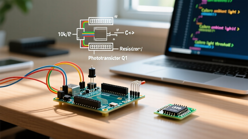
For this tutorial, we are using the Vishay BPW85B (or pin-compatible equivalents) with a 10kΩ pull-down resistor for standard indoor prototyping.
- Identify the Pins: The longer lead is the Collector. The shorter lead (often with a flat spot on the plastic lens rim) is the Emitter.
- Connect the Collector: Wire the longer lead directly to the Arduino's 5V pin.
- Connect the Emitter: Wire the shorter lead to a breadboard row shared by a 10kΩ resistor and a jumper wire to Analog Pin A0.
- Complete the Ground: Connect the other end of the 10kΩ resistor to the Arduino's GND.
- Add a Bypass Capacitor (Optional but Recommended): Place a 100nF (0.1µF) ceramic capacitor in parallel with the 10kΩ resistor. This creates a low-pass filter that drastically reduces high-frequency noise and 50/60Hz mains flicker from fluorescent or LED room lighting.
Advanced Arduino C++ Implementation
Raw analog readings from a phototransistor are rarely perfectly stable due to environmental light flicker (especially from AC-powered LEDs) and electromagnetic interference. The following code implements an Exponential Moving Average (EMA) filter to smooth the data without introducing the lag associated with simple delay-based averaging.
// Arduino Phototransistor EMA Filtering Code
#define SENSOR_PIN A0
#define LED_PIN 13

// EMA Filter parameters
const float alpha = 0.05; // Lower = smoother but more lag (0.01 to 0.1)
float smoothedValue = 0;
bool filterInitialized = false;

void setup() {
  Serial.begin(115200);
  pinMode(LED_PIN, OUTPUT);
  analogReference(DEFAULT); // Ensure 5V reference on standard boards
}

void loop() {
  int rawReading = analogRead(SENSOR_PIN);

  // Initialize filter on first run to prevent startup lag
  if (!filterInitialized) {
    smoothedValue = rawReading;
    filterInitialized = true;
  }

  // Apply Exponential Moving Average
  smoothedValue = (alpha * rawReading) + ((1.0 - alpha) * smoothedValue);

  // Map smoothed value to a 0-100 percentage scale
  // Adjust 800 based on your specific pull-down resistor and max light level
  int lightPercentage = map((int)smoothedValue, 0, 800, 0, 100);
  lightPercentage = constrain(lightPercentage, 0, 100);

  Serial.print("Raw: ");
  Serial.print(rawReading);
  Serial.print(" | Smoothed: ");
  Serial.print(smoothedValue, 2);
  Serial.print(" | Light: ");
  Serial.print(lightPercentage);
  Serial.println("%");

  // Trigger an action if it gets too dark
  if (lightPercentage < 15) {
    digitalWrite(LED_PIN, HIGH);
  } else {
    digitalWrite(LED_PIN, LOW);
  }

  delay(20); // 50Hz sample rate
}
Understanding the Analog Input Mapping
The map() function's upper bound (set to 800 in the code above) must be calibrated to your specific hardware. Because a phototransistor never truly outputs 0 current in absolute darkness (due to "dark current", typically in the nanoamp range), your baseline will rarely be a perfect 0. Similarly, it may saturate before hitting the full 1023 ADC limit depending on the 5V rail's exact tolerance.
Calibration Procedure for Production
If you are moving from a breadboard prototype to a manufactured PCB, you must calibrate the sensor thresholds:
- Capture Dark Current: Cover the sensor completely with electrical tape or a dark enclosure. Record the raw ADC value. This is your
ZERO_OFFSET. - Capture Saturation Point: Expose the sensor to the maximum expected illumination (e.g., direct sunlight or the target LED emitter). Record the raw ADC value. This is your
MAX_SCALE. - Update the Code: Replace the
0, 800in the map function withZERO_OFFSET, MAX_SCALEto ensure the full 0-100% range is utilized accurately.
Real-World Failure Modes and Troubleshooting
Even with a correct schematic, environmental factors can cause erratic behavior. Here is how to diagnose the most common edge cases:
1. The Sensor is Saturated (Reads 1023 Constantly)
Cause: The pull-down resistor is too large for the ambient light level, causing the voltage drop to exceed the Arduino's 5V reference limit.
Fix: Drop the pull-down resistor value. If you are using 100kΩ, swap it for 10kΩ. If using 10kΩ, drop to 2.2kΩ or 1kΩ.
2. Erratic Spikes in Readings (Noise)
Cause: The high-impedance nature of the phototransistor circuit acts as an antenna for EMI (Electromagnetic Interference) from nearby switching power supplies or AC wiring.
Fix: Ensure the 100nF bypass capacitor is placed as physically close to the Arduino's analog pin and ground as possible. Keep analog traces short on custom PCBs.
3. TV Remote Causes False Triggers
Cause: If you are using an IR-sensitive phototransistor (like the BPW85B) for visible light sensing, the 38kHz or 40kHz carrier signal from an IR remote will flood the junction, causing massive voltage spikes.
Fix: Switch to a visible-light-only sensor like the TEPT5600, or apply a piece of exposed, undeveloped photographic film (or a specialized IR-blocking optical filter) over the lens to block wavelengths above 750nm.
4. 50Hz/60Hz Mains Flicker
Cause: AC-powered LED and fluorescent lights pulse at twice the mains frequency (100Hz or 120Hz). A fast phototransistor will detect this flicker, causing your Arduino to read a constantly oscillating value.
Fix: The EMA filter provided in the code above handles this digitally. For a hardware fix, increase the bypass capacitor from 100nF to 1µF or 4.7µF to create a heavier analog low-pass filter that averages out the optical ripple.
Summary
Integrating a phototransistor with an Arduino provides a robust, high-speed alternative to legacy photoresistors. By carefully selecting the spectral response of your component, sizing the pull-down resistor to match your target lux environment, and implementing digital smoothing techniques like the EMA filter, you can achieve laboratory-grade light sensing on a maker budget. Always remember to account for dark current offsets and IR interference when deploying your circuit outside the controlled environment of your workbench.