
The Voltage Gap: Why Direct Connection Destroys Microcontrollers
Integrating legacy industrial equipment, older GPS modules, or commercial PLCs with modern microcontrollers requires bridging a fundamental electrical divide. The RS-232 standard (officially TIA-232) was designed in the 1960s for long-distance, noise-resistant communication over unshielded twisted pair cables. To achieve this, it uses high-voltage, inverted logic levels that are fundamentally incompatible with modern silicon.
An Arduino Uno (based on the ATmega328P) operates on 5V TTL logic, where a logic HIGH is 5V and a logic LOW is 0V. In stark contrast, the RS-232 specification defines a logic '1' (Mark) as a negative voltage between -3V and -15V, and a logic '0' (Space) as a positive voltage between +3V and +15V. Connecting an RS-232 transmit line directly to an Arduino GPIO pin will inject negative voltage and overvoltage into the microcontroller, instantly destroying the silicon lattice and permanently bricking the board. A dedicated level-shifting transceiver is strictly required.
Selecting the Right Transceiver: MAX232 vs. MAX3232 in 2026
Historically, the MAX232 chip was the default solution for 5V TTL-to-RS232 conversion. However, as the maker ecosystem has shifted heavily toward 3.3V logic architectures (like the Arduino Zero, Due, and ESP32), the MAX232 has become largely obsolete for new designs. The modern standard is the MAX3232, which supports a wider supply voltage range (3.0V to 5.5V) and utilizes smaller charge pump capacitors.
| Feature | MAX232 (Legacy) | MAX3232 (Modern Standard) | ADM3251 (Industrial) |
|---|---|---|---|
| Operating Voltage | 5.0V Only | 3.0V to 5.5V | 3.0V to 5.5V |
| Charge Pump Capacitors | 4x 1.0µF (Tantalum/Electrolytic) | 4x 0.1µF (100nF Ceramic) | Internal / Isolated |
| Galvanic Isolation | No | No | Yes (2.5kV RMS) |
| Typical Module Cost (2026) | $3.50 - $6.00 | $2.50 - $4.00 | $12.00 - $18.00 |
| Best Use Case | Retro-computing, 5V-only repairs | Arduino Uno, Mega, ESP32, Zero | Industrial PLCs, Motor Controllers |
For 95% of hobbyist and prototyping applications, a pre-assembled MAX3232 breakout board is the correct choice. These modules integrate the four necessary 100nF surface-mount charge pump capacitors, saving you from the tedious through-hole soldering required by bare DIP chips.
Hardware Configuration: Wiring the MAX3232 to Arduino Uno
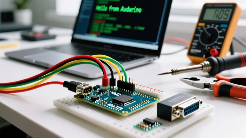
When configuring your RS232 Arduino circuit, precise pin mapping is critical. The MAX3232 module features TTL-side pins (which connect to the Arduino) and DB9-side pins (which connect to the RS-232 device).
- VCC: Connect to the Arduino 5V pin (or 3.3V pin if using an Arduino Zero/ESP32). The MAX3232 will automatically generate the required +/- 10V rails internally via its charge pump.
- GND: Connect to the Arduino GND pin. Never omit the ground connection; RS-232 relies on a shared ground reference for signal integrity.
- T1IN (TTL Transmit In): Connect to your designated Arduino TX pin (e.g., Pin 11 if using SoftwareSerial).
- R1OUT (TTL Receive Out): Connect to your designated Arduino RX pin (e.g., Pin 10 if using SoftwareSerial).
- T1OUT (RS232 Transmit Out): Connect to the RX pin of your external RS-232 device (Pin 2 on a standard DB9 connector).
- R1IN (RS232 Receive In): Connect to the TX pin of your external RS-232 device (Pin 3 on a standard DB9 connector).
Software Configuration: Bypassing Hardware Serial Limitations
The Arduino Uno possesses only one hardware UART (Universal Asynchronous Receiver-Transmitter), which is tied to pins 0 (RX) and 1 (TX). Because this same UART is routed through the onboard ATmega16U2 USB-to-Serial chip, using it for RS-232 communication will cause conflicts when uploading sketches or using the Serial Monitor for debugging.
The standard configuration strategy is to utilize the SoftwareSerial library, which bit-bangs serial communication on any digital pins. We will configure pins 10 and 11 for the RS-232 link, leaving pins 0 and 1 free for USB debugging.
#include <SoftwareSerial.h>

// Configure SoftwareSerial: RX on Pin 10, TX on Pin 11
SoftwareSerial rs232(10, 11);

void setup() {
  // Initialize hardware serial for USB debugging
  Serial.begin(9600);

  // Initialize software serial for RS232 communication
  rs232.begin(9600);

  Serial.println("RS232 Arduino Bridge Initialized.");
}

void loop() {
  // Forward data from RS232 device to USB Serial Monitor
  if (rs232.available()) {
    Serial.write(rs232.read());
  }

  // Forward data from USB Serial Monitor to RS232 device
  if (Serial.available()) {
    rs232.write(Serial.read());
  }
}
The Baud Rate Bottleneck
When using SoftwareSerial on 16MHz AVR-based boards (Uno, Nano, Mega), reliable communication is practically capped at 57,600 baud. Pushing the configuration to 115,200 baud will result in severe character dropping and timing drift due to CPU interrupt overhead. If your RS-232 application strictly requires 115,200 baud or higher, you must upgrade to an Arduino Mega 2560 (which features three extra hardware UARTs) or an ESP32, and wire the MAX3232 directly to the dedicated hardware RX/TX pins.
Advanced Troubleshooting and Edge Cases
Even with correct wiring and code, RS-232 networks present unique physical layer challenges that do not exist in modern USB or I2C setups.
DTE vs. DCE: The Null Modem Edge Case
RS-232 devices are classified as either Data Terminal Equipment (DTE, like a PC or Arduino) or Data Circuit-terminating Equipment (DCE, like a modem or sensor). Standard straight-through cables connect a DTE to a DCE (TX to RX, RX to TX). However, if you are connecting your Arduino (DTE) to another DTE device (like a CNC controller or a secondary PC), you must cross the lines. This requires a Null Modem configuration, where the MAX3232 T1OUT connects to the device's TX pin, and R1IN connects to the device's RX pin.
Industrial Ground Loops and Isolation
When connecting an Arduino to heavy industrial machinery (like a VFD or a large PLC), the ground potential between the two devices can vary by several volts due to high-current switching. This potential difference will force current through the MAX3232 ground pin, destroying the chip and potentially the Arduino.
Safety Warning: Never connect a standard, non-isolated MAX3232 module directly to industrial 24V/120V control systems. For these environments, you must use an isolated RS-232 transceiver (such as the ADM3251) or place a digital isolator (like the ISO7721) between the Arduino GPIO pins and the TTL side of the MAX3232.
References and Further Reading
- Texas Instruments MAX3232 Datasheet - Official electrical characteristics, charge pump capacitor requirements, and voltage thresholds.
- Arduino SoftwareSerial Reference - Official documentation on library limitations, baud rate constraints, and pin restrictions for AVR architectures.
- SparkFun Serial Communication Guide - Comprehensive overview of UART protocols, DTE/DCE classifications, and physical layer signaling.