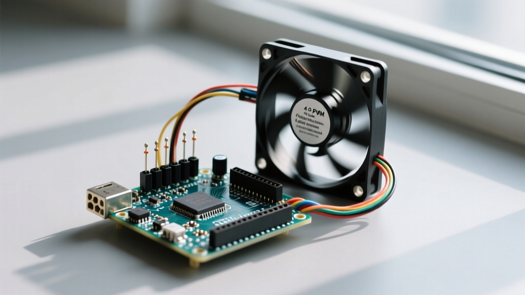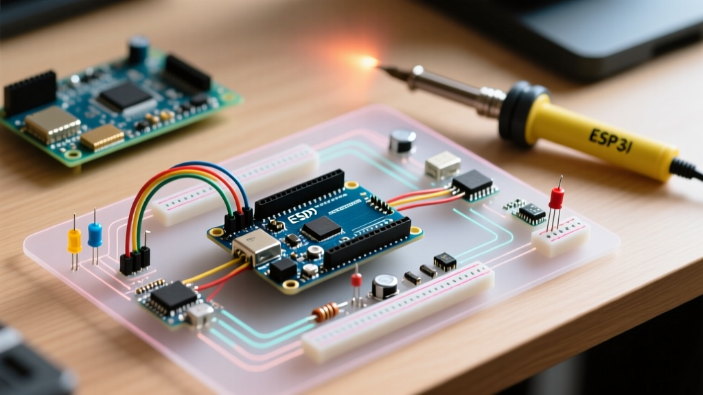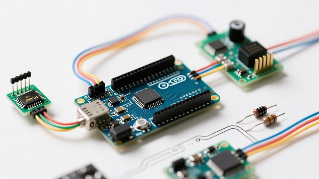

The Workflow Bottleneck: Why Piezo Integrations Fail
Integrating a piezo with Arduino boards is a classic rite of passage for makers, but it frequently devolves into a frustrating cycle of trial and error. The standard workflow—taping a bare piezo disc to a surface, wiring it directly to an analog pin, and writing a basic analogRead() loop—almost always results in false triggers, missed transients, and fried microcontroller pins. The high impedance and massive voltage spikes generated by piezoelectric materials require a disciplined engineering approach.
This guide replaces the guesswork with a streamlined, four-phase workflow optimization strategy. By standardizing your hardware bill of materials (BOM), implementing proper signal conditioning, and optimizing the Arduino ADC (Analog-to-Digital Converter) sampling rate, you can reduce your prototyping time from days to hours while achieving industrial-grade knock and vibration detection.
Phase 1: Standardizing the Hardware BOM
Stop sourcing random piezo buzzers from salvaged electronics. For reliable sensor data, you need a dedicated piezoelectric transducer optimized for mechanical deformation, not acoustic output. As of 2026, the following BOM represents the most cost-effective and reliable baseline for rapid prototyping, totaling under $15 per node.
- Sensor Element: Murata 7BB-20-6L0 (20mm diameter, 6kHz resonant frequency). Priced around $1.45, this brass-substrate disc offers a highly predictable voltage-to-strain curve compared to cheaper nickel alternatives.
- Pull-Down Resistor: 1MΩ (Metal Film, 1% tolerance). This bleeds off the parasitic charge that accumulates on the piezo element, resetting the baseline to 0V immediately after a strike.
- Current Limiting Resistor: 10kΩ series resistor to protect the Arduino's internal ADC multiplexer from instantaneous current surges.
- Voltage Clamping: BZX55C5V1 (5.1V Zener Diode). A hard strike on a 20mm piezo can easily generate 50V to 90V. The Zener diode clamps the signal to a safe 5.1V, protecting your ATmega328P or SAMD21 silicon.
Phase 2: Signal Conditioning Matrix
Before writing a single line of code, you must decide on your signal conditioning topology based on your project's noise environment. The table below outlines the three primary workflows, allowing you to select the right circuit complexity for your specific use case.
| Topology | Components Required | Best Use Case | Drawbacks |
|---|---|---|---|
| Raw Clamped (Baseline) | 1MΩ pull-down, 10kΩ series, 5.1V Zener | Simple knock switches, door knock detectors in quiet environments. | Susceptible to EMI; requires heavy software filtering. |
| RC Low-Pass Filtered | Baseline + 100nF ceramic capacitor (parallel) | Vibration monitoring, continuous machinery health tracking. | Attenuates sharp, high-frequency impact transients. |
| Op-Amp Buffered (Advanced) | Baseline + LM358 or MCP6002 non-inverting amp | Acoustic emission testing, high-precision structural strain. | Increases BOM cost by ~$0.80 and requires dual-rail or virtual ground. |
For 90% of general maker applications, the Raw Clamped topology provides the best balance of speed and reliability. According to SparkFun's Piezo Vibration Sensor Hookup Guide, the 1MΩ pull-down resistor is non-negotiable; without it, the piezo acts as a capacitor, holding a charge and causing the Arduino's analog pin to float unpredictably for seconds after an impact.
Phase 3: Firmware Optimization & ADC Prescaling
The most critical, yet widely ignored, bottleneck in the piezo with Arduino workflow is the default ADC sampling speed. By default, the Arduino analogRead() function takes approximately 104 microseconds (µs) per sample. This translates to a sampling rate of roughly 9.6 kHz. While adequate for reading a potentiometer, a sharp mechanical knock produces a transient spike that may last only 1 to 3 milliseconds. At 9.6 kHz, your microcontroller might completely miss the peak amplitude of the strike.
To optimize your workflow, you must increase the ADC clock speed by adjusting the ADCSRA (ADC Control and Status Register A) prescaler. The default prescaler is 128. By dropping it to 16, you can push the sampling rate to nearly 76 kHz without sacrificing meaningful 10-bit resolution.
Workflow Pro-Tip: Bitwise ADC Optimization
Insert this single line of code in yoursetup()function to change the prescaler. This eliminates the need for external ADC chips in high-speed vibration logging.ADCSRA = (ADCSRA & 0xf8) | 0x04; // Sets prescaler to 16
For deeper insights into microcontroller analog pins and ADC timing, refer to the official Arduino Analog Pins documentation.
Implementing a Ring Buffer for Peak Detection
Instead of relying on a single analogRead() value, optimize your firmware by implementing a lightweight ring buffer. This allows the Arduino to capture the absolute maximum voltage spike of a knock event over a 5ms window, completely eliminating the 'missed trigger' bug that plagues beginners.
- Initialize an integer array of 50 elements.
- Read the analog pin continuously, storing values in the array using a modulo index.
- Scan the array for the maximum value only when a baseline threshold (e.g., >50) is breached.
- Reset the array and trigger your event logic.
Phase 4: Dynamic Thresholding Workflow
Hardcoding a trigger threshold (e.g., if (sensorValue > 500)) is a fragile workflow. Temperature fluctuations, humidity, and mechanical creep in the mounting adhesive will shift the piezo's baseline and sensitivity over time. To build a robust system, implement a dynamic thresholding algorithm using a running average.
Calculate an Exponential Moving Average (EMA) of the background noise floor. Set your trigger threshold to EMA + (Standard_Deviation * 4). This ensures that your piezo with Arduino setup remains perfectly calibrated whether it is mounted on a quiet wooden desk or a vibrating 3D printer frame. This statistical approach, detailed in advanced signal processing texts like those referenced by All About Circuits, transforms a finicky toy into a reliable industrial sensor.
Edge Cases & Failure Modes to Anticipate
Even with an optimized workflow, physical deployment introduces variables that software cannot fix. Keep this troubleshooting matrix handy during your integration phase:
- Parasitic Capacitance in Long Cables: If your piezo is mounted more than 12 inches from the Arduino, the shielded cable will act as a capacitor, filtering out high-frequency knock data. Solution: Solder a small JFET source-follower buffer directly to the piezo terminals to lower the output impedance before the signal travels down the cable.
- Adhesive Dampening: Using thick double-sided foam tape will absorb the mechanical strain before it reaches the brass substrate. Solution: Use a thin layer of cyanoacrylate (super glue) or rigid epoxy for high-frequency transient detection. Use foam tape only if you specifically want to filter out high frequencies and measure low-frequency rumble.
- Acoustic Crosstalk: If using multiple piezos on the same surface (e.g., a multi-zone electronic drum kit), a strike on Zone A will travel through the material and trigger Zone B. Solution: Implement a software 'masking' window. When Zone A triggers, ignore all inputs from Zone B for 15 milliseconds.
Frequently Asked Questions
Can I use an active piezo buzzer as a sensor?
Technically yes, but it is highly discouraged for optimized workflows. Active buzzers contain an internal oscillator circuit that interferes with incoming mechanical strain signals, resulting in a highly non-linear and unpredictable voltage output. Always use passive piezo discs or dedicated piezo film sensors (like TE Connectivity's LDT series) for sensing applications.
Why is my Arduino resetting when I hit the piezo?
A severe mechanical strike on an unclamped 27mm piezo disc can generate upwards of 100V. If you omit the Zener diode and series resistor from the BOM, this high-voltage spike will backfeed through the Arduino's internal protection diodes, directly into the 5V rail, causing a brownout reset or permanently destroying the microcontroller's ADC multiplexer. Always clamp the signal.
What is the optimal analog reference voltage for piezos?
For maximum resolution in low-vibration environments, switch your Arduino's analog reference from the default 5V to the internal 1.1V reference using analogReference(INTERNAL);. This maps the 10-bit ADC range (0-1023) to 0-1.1V, vastly increasing the sensitivity for detecting micro-vibrations, provided your Zener clamping circuit is adjusted accordingly to prevent overvoltage.