
The Hidden Hardware Trap: Why Arduino and Sensors Fail to Communicate
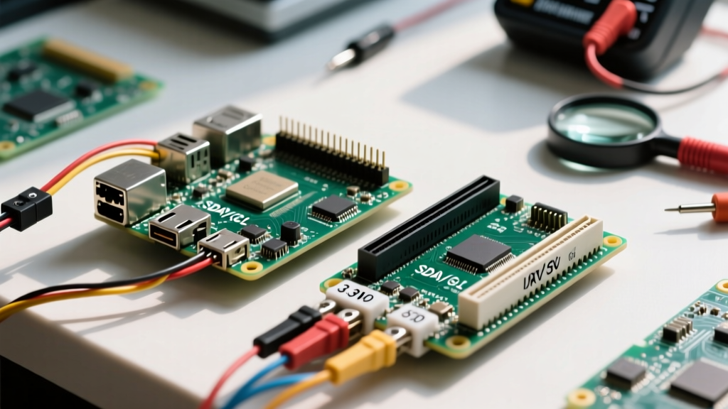
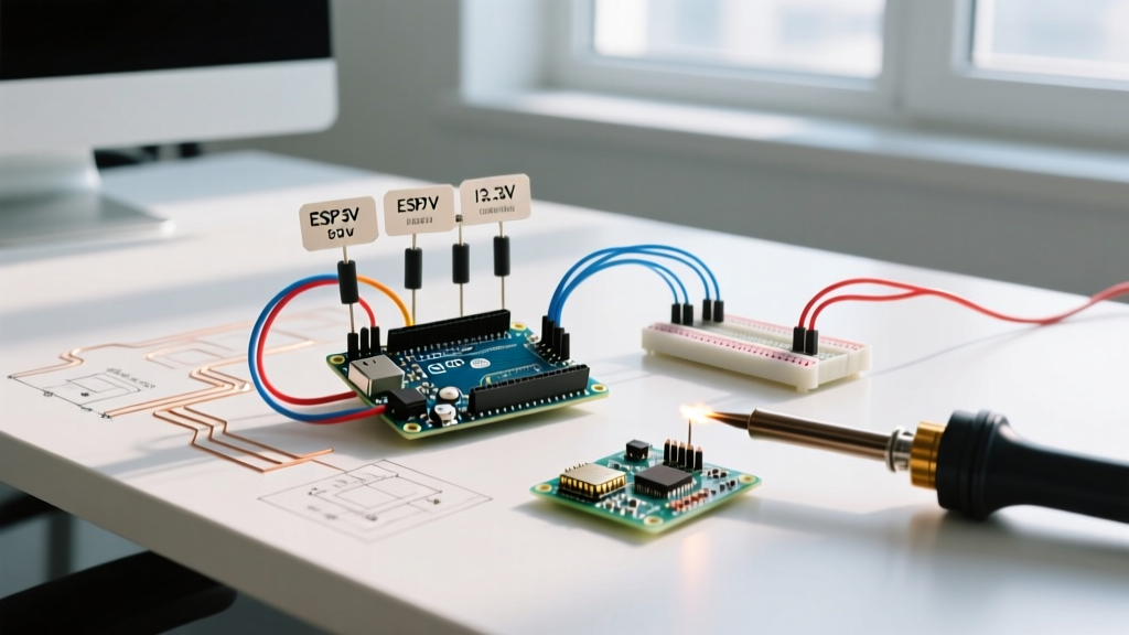
When integrating Arduino and sensors into a unified embedded system, the most common point of failure is rarely the C++ sketch. Instead, it is the physical layer: logic level mismatches, protocol timing violations, and power budget overruns. As of 2026, the maker market is flooded with advanced environmental, spatial, and gas sensors that operate on strict 1.8V or 3.3V logic, while legacy and entry-level Arduino boards (like the Uno R3) still default to 5V TTL. Forcing a 5V signal into a 3.3V sensor input doesn't just cause erratic readings; it permanently degrades silicon gates and destroys sensitive polymer sensing elements.
This compatibility guide dissects the electrical and protocol-level requirements for pairing Arduinos with modern sensors, providing actionable frameworks to prevent hardware damage and ensure reliable data acquisition.
Decoding Logic Levels: 5V Tolerance vs. 3.3V Strictness
The foundation of sensor compatibility lies in understanding Voltage Input High (V_IH) and Voltage Input Low (V_IL) thresholds. A classic ATmega328P-based Arduino Uno outputs ~4.8V on a HIGH digital pin. If your sensor is not explicitly labeled "5V tolerant," feeding this voltage into its SDA, SCK, or MOSI pins will exceed the absolute maximum ratings of the sensor's internal CMOS transistors.
Expert Warning: Connecting a 3.3V Bosch BME280 directly to a 5V Arduino I2C bus without a level shifter will not immediately fry the chip. However, the 5V logic will slowly degrade the sensor's internal humidity-sensitive polymer layer and stress the internal voltage regulator, leading to permanent humidity drift within 3 to 6 months of continuous operation. Always use a bidirectional level shifter for I2C environmental sensors.
Microcontroller Logic Profiles
- Arduino Uno R3 (ATmega328P): 5V logic. Requires level shifting down for 90% of modern SPI/I2C sensors.
- Arduino Nano 33 IoT (SAMD21): 3.3V logic. Native compatibility with almost all modern sensors, but lacks 5V tolerance on inputs.
- Arduino Uno R4 Minima (RA4M1): 3.3V logic internally, but features 5V-tolerant I/O pins on specific ports. Requires careful cross-referencing with the pinout diagram before connecting 5V sensors.
Protocol Compatibility Matrix
Different sensor protocols impose unique constraints on the Arduino's hardware peripherals. Below is a compatibility matrix detailing the electrical requirements for standard sensor interfaces.
| Protocol | Typical Sensors | Pull-Up Resistors | Max Speed (Arduino) | Compatibility Notes |
|---|---|---|---|---|
| I2C | BME280, MPU6050, VL53L1X | 4.7kΩ to VCC | 400 kHz (Fast Mode) | Requires bidirectional level shifting. Internal pull-ups (20kΩ-50kΩ) are too weak for reliable bus capacitance. |
| SPI | ADXL345, MAX31856, W25Q128 | 10kΩ on CS (Pull-Up) | 8 MHz (Hardware SPI) | Unidirectional level shifting (CD4050B) is sufficient for MOSI/SCK/CS. MISO requires 3.3V to 5V translation. |
| UART | TF-Luna LiDAR, GPS NEO-M9N | None required | 115,200 Baud | Use voltage dividers on Arduino TX to Sensor RX. Sensor TX to Arduino RX is usually safe if Arduino V_IH is 3.0V. |
| 1-Wire | DS18B20, MAX31850 | 4.7kΩ to VCC | 15.4 kbps | Parasitic power mode requires a strong pull-up (MOSFET driven) during temperature conversion to supply ~1.5mA peak. |
For comprehensive protocol timing diagrams and bus capacitance limits, refer to the official Arduino I2C Communication Guide.
Power Budgeting: When the Arduino 5V Pin Fails
A critical, often overlooked aspect of Arduino and sensors compatibility is the current limit of the onboard voltage regulator. Many makers power high-draw sensors directly from the Arduino's 5V pin. On a standard Uno R3 powered via the barrel jack (9V input), the onboard AMS1117-5.0 linear regulator must dissipate the voltage difference as heat.
The Thermal Shutdown Threshold
If your sensor array draws more than 200mA continuously at a 9V input, the AMS1117 will reach its thermal junction limit (~125°C) and trigger internal thermal shutdown. The Arduino will randomly reset, and the sensor will brown out.
- Low Draw (Safe for Arduino 5V Pin): BME680 (~3mA), DS18B20 (~1.5mA), MPU6050 (~3.9mA).
- High Draw (Requires External Power): MQ-135 Gas Sensor (Heater draws ~150mA), TF-Luna LiDAR (~140mA peak), Nextion HMI Displays (up to 350mA).
Actionable Solution: For high-draw sensors, bypass the Arduino regulator entirely. Use an external switching buck converter (like the MP1584EN, priced around $1.50) to step down a 9V or 12V wall adapter directly to 5V, wiring the sensor's VCC directly to the buck converter output while sharing a common ground with the Arduino.
Level Shifting Hardware Compared (2026 Market)
When bridging 5V Arduinos and 3.3V sensors, selecting the right translation IC is paramount. Not all level shifters handle I2C pull-up speeds correctly.
- BSS138 MOSFET Breakout (Bidirectional): The gold standard for I2C. Uses N-channel MOSFETs to translate levels without distorting the I2C rise times. Cost: ~$1.20.
- CD4050B Hex Buffer (Unidirectional): Excellent for SPI (MOSI, SCK, CS) and UART TX. Cannot be used for I2C because it cannot handle bidirectional data lines. Cost: ~$0.40.
- TXS0108E (Auto-Directional): Features internal one-shot timers for edge acceleration. While great for UART and SPI, it is notorious for failing on standard I2C buses because its internal pull-ups conflict with external I2C pull-ups, causing bus lockups. Cost: ~$2.50.
For deeper silicon-level translation mechanics, Texas Instruments provides excellent application notes on Voltage Logic Translation between mismatched CMOS families.
Real-World Sensor Compatibility Case Studies
Case Study 1: Bosch BME280 Environmental Sensor
The Bosch BME280 is a staple for weather stations. It supports both I2C and SPI. Compatibility Trap: Many cheap breakout boards include a 3.3V LDO (like the HT7133) for power, leading makers to believe the logic pins are also 5V tolerant. They are not. The SDA/SCL lines connect directly to the BME280 silicon. You must power the board with 3.3V or 5V (if the LDO is present), but you must use a BSS138 level shifter on the I2C data lines if using a 5V Arduino.
Case Study 2: MQ-135 Air Quality Sensor
The MQ-135 relies on a tin dioxide (SnO2) layer that requires a heated environment to react with gases. Compatibility Trap: The onboard heater draws roughly 150mA. Furthermore, the analog output voltage scales with the sensor's supply voltage. If you power it from the Arduino's USB 5V line, voltage droop from the USB port will cause the analog reading to drift wildly. Solution: Power the MQ-135 from a dedicated 5V rail and use the Arduino's default 5V reference (or an external 4.096V precision reference) for the ADC to ensure stable PPM calculations.
Case Study 3: DS18B20 Waterproof Temperature Probe
Compatibility Trap: Using "Parasitic Power Mode" (connecting VDD to GND) to save a wire. In this mode, the sensor draws power from the data line via a capacitor during the temperature conversion phase. The standard 4.7kΩ pull-up resistor cannot supply the required 1.5mA, causing the conversion to abort and return 85°C (the default power-on register value). Solution: Always use the standard 3-wire connection (VCC, GND, Data) for reliable readings, or implement an active MOSFET pull-up circuit if parasitic mode is strictly required.
Frequently Asked Questions
Why does the I2C Scanner return no addresses when my sensor is wired correctly?
This is almost always a pull-up resistor issue or a logic level mismatch. If your sensor breakout board lacks onboard pull-ups, the I2C bus capacitance will prevent the signal from reaching the V_IH threshold in time for the clock cycle. Add external 4.7kΩ resistors from SDA and SCL to the sensor's VCC (3.3V), placed after the level shifter on the 3.3V side.
Can I use a simple voltage divider for I2C level shifting?
No. A voltage divider (e.g., 2.2kΩ and 3.3kΩ) works for unidirectional signals like SPI MOSI or UART TX. However, I2C requires the sensor to pull the SDA line LOW to acknowledge (ACK). A voltage divider will create a voltage conflict when the sensor tries to pull the line low against the Arduino's 5V HIGH output, resulting in a bus lockup and potential damage to the sensor's open-drain MOSFET.
My SPI sensor reads all 0xFF. What is the hardware fault?
Reading 0xFF indicates the MISO line is floating HIGH or the sensor is not responding to the clock. First, verify the SPI Mode (CPOL/CPHA) in your library matches the sensor datasheet. Second, ensure the Chip Select (CS) line is being pulled LOW before the transaction. Third, check if the 3.3V MISO signal is successfully crossing the V_IH threshold of your 5V Arduino; you may need a high-speed logic translator like the SN74LVC1T45 on the MISO line.