
Why Replace Mechanical Pots with a Digital Potentiometer Arduino Setup?
Mechanical potentiometers are a staple in electronics, but they come with inherent physical limitations. They suffer from contact wear, introduce scratchy noise during adjustment, and are highly susceptible to environmental factors like dust and vibration. More importantly, they cannot be automated. When your project requires dynamic, software-controlled resistance adjustments—such as programmable gain amplifiers, automated audio mixing, or precision voltage trimming—a digital potentiometer Arduino integration becomes essential.
Unlike mechanical variants, digital potentiometers (digipots) use an internal resistor ladder and CMOS switches to select the wiper position. In this comprehensive guide, we will walk through the exact hardware wiring, logic-level considerations, and C++ code required to interface a Microchip MCP41010 10kΩ SPI digital potentiometer with an Arduino microcontroller.
Choosing the Right IC: SPI vs. I2C Digital Potentiometers
Before wiring your breadboard, it is crucial to select the correct integrated circuit. Digital potentiometers generally communicate via SPI (Serial Peripheral Interface) or I2C (Inter-Integrated Circuit). SPI digipots like the MCP41010 offer faster update rates and simpler command structures, while I2C models like the Analog Devices AD5242 allow you to daisy-chain multiple devices on the same two bus wires.
| Model | Interface | Channels | Resolution | Approx. Price (2026) |
|---|---|---|---|---|
| Microchip MCP41010 | SPI | Single | 256 Steps (8-bit) | $1.85 |
| Microchip MCP4231 | SPI | Dual | 129 Steps (7-bit + 1) | $2.10 |
| Analog Devices AD5242 | I2C | Dual | 256 Steps (8-bit) | $3.40 |
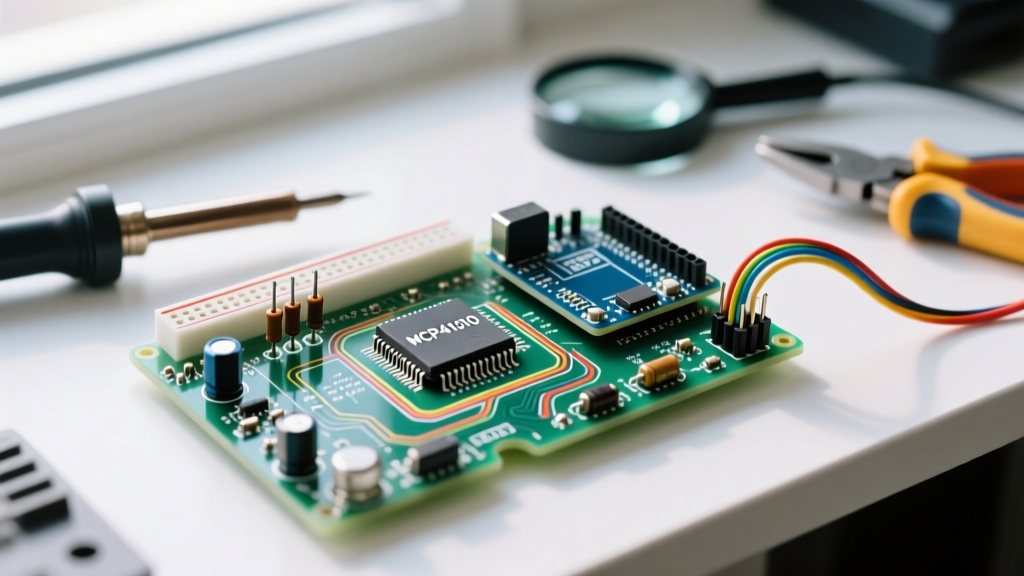
For this tutorial, we are focusing on the Microchip MCP41010. It is housed in a standard 8-pin DIP package, making it incredibly breadboard-friendly for prototyping, and its 10kΩ end-to-end resistance is ideal for standard 5V logic signal scaling.
Hardware Wiring: Interfacing the MCP41010 via SPI
The MCP41010 requires four primary connections to your Arduino's SPI bus. Below is the exact pinout mapping for an Arduino Uno or Nano (ATmega328P-based boards).
- Pin 1 (CS): Chip Select / Slave Select → Arduino Pin 10
- Pin 2 (SCK): Serial Clock → Arduino Pin 13
- Pin 3 (SI): Serial Data In (MOSI) → Arduino Pin 11
- Pin 4 (VSS): Ground → Arduino GND
- Pin 5 (PA0): Resistor Terminal A → Signal Input (e.g., 0-5V)
- Pin 6 (PW0): Wiper Output → Analog Output to your circuit
- Pin 7 (PB0): Resistor Terminal B → Ground (for voltage divider) or Signal
- Pin 8 (VDD): Power Supply → Arduino 5V
⚠️ Critical 3.3V Logic Warning for Modern MCUs
If you are using a 3.3V microcontroller (like the Arduino Nano 33 IoT, ESP32, or Raspberry Pi Pico), you cannot wire the MCP41010 directly. The MCP41010 is a 5V part, and its Logic High threshold ($V_{IH}$) is typically $0.7 \times V_{DD}$, meaning it requires at least 3.5V to register a HIGH signal. A 3.3V MCU will fail to trigger the SPI commands reliably. You must use a logic level shifter (such as a 74LVC245 or a dedicated bi-directional MOSFET shifter module) on the CS, SCK, and SI lines.
The Importance of Hardware Decoupling
Digital potentiometers switch internal CMOS gates at high speeds during SPI transactions, which can inject high-frequency noise back into your power rail. Always place a 100nF (0.1µF) ceramic decoupling capacitor directly across Pin 8 (VDD) and Pin 4 (VSS). The physical distance between the capacitor leads and the IC pins should not exceed 3mm to minimize parasitic inductance.
Step-by-Step Arduino Code Implementation
Controlling the MCP41010 requires sending a 16-bit data stream over SPI. This stream is divided into two bytes: the Command Byte and the Data Byte. According to the Arduino SPI Reference, we use the built-in SPI library to handle the clock timing and data shifting.
#include <SPI.h>

const int CS_PIN = 10; // Chip Select Pin

void setup() {
  pinMode(CS_PIN, OUTPUT);
  digitalWrite(CS_PIN, HIGH); // Deselect the chip initially

  SPI.begin();
  // MCP41010 max clock is 10MHz, Arduino default is 4MHz (safe)
  SPI.setBitOrder(MSBFIRST);
  SPI.setDataMode(SPI_MODE0);

  Serial.begin(9600);
  Serial.println("MCP41010 Digital Potentiometer Initialized.");
}

void loop() {
  // Sweep the wiper from 0 to 255 (Max Resistance to Min Resistance)
  for (int i = 0; i <= 255; i++) {
    setWiper(i);
    delay(20);
  }

  // Sweep back down
  for (int i = 255; i >= 0; i--) {
    setWiper(i);
    delay(20);
  }
}

void setWiper(int value) {
  // Constrain value to 8-bit range
  value = constrain(value, 0, 255);

  digitalWrite(CS_PIN, LOW); // Enable SPI communication

  // Command Byte: 00010001 (0x11)
  // Bits 7-6: 00 (Write Data)
  // Bits 5-4: 01 (Select Potentiometer 0)
  // Bits 3-0: 0001 (Don't care for single pot, standard padding)
  SPI.transfer(0x11);

  // Data Byte: The actual wiper position (0-255)
  SPI.transfer(value);

  digitalWrite(CS_PIN, HIGH); // Latch the data and end communication
}
Understanding the Math: Calculating Output Resistance
The MCP41010 is a 10kΩ potentiometer with 256 steps. However, the wiper itself has an internal resistance ($R_W$) of approximately 125Ω. When calculating the exact resistance between the Wiper (PW0) and Terminal B (PB0), use the following formula:
$R_{WB} = (D / 256) \times R_{AB} + R_W$
Where D is the decimal value (0-255) sent via SPI, R_AB is 10,000Ω, and R_W is ~125Ω.
If you send a value of 0, the resistance will not be 0Ω; it will be roughly 125Ω. This is a common trap for makers attempting to use digipots as exact zero-ohm switches.
Critical Edge Cases and Hardware Limitations
While digital potentiometers are incredibly useful, they are not a drop-in replacement for mechanical pots in high-power circuits. You must respect the silicon limits of the IC.
1. The Wiper Current Limit
The internal CMOS switches of the MCP41010 are microscopic. The absolute maximum continuous current allowed through the wiper pin is ±1 mA. If you attempt to use the digipot to directly dim an LED or control the base current of a power transistor without a buffer, you will permanently destroy the wiper trace. Always use an op-amp buffer (like the MCP6001 or LM358) if your load requires more than 1 mA.
2. Voltage Boundary Restrictions
The analog signals present on pins PA0, PW0, and PB0 must strictly remain between $V_{SS}$ (GND) and $V_{DD}$ (5V). If you attempt to pass an AC audio signal that swings below 0V (e.g., -1V to +1V), the internal ESD protection diodes will conduct, clipping your signal and potentially latching up the IC. For AC signals, you must bias the signal to $V_{DD}/2$ (2.5V) using a DC offset circuit before it enters the digipot.
3. Power-On Reset (POR) State
When the MCP41010 is first powered on, its internal volatile memory defaults to the mid-scale position (Step 128, or exactly 50% resistance). If your circuit requires a specific safe-state resistance upon boot (such as minimum volume in an audio amplifier to prevent speaker pops), your Arduino setup() function must immediately send the desired SPI command before any other initialization routines occur.
Frequently Asked Questions
Can I use a digital potentiometer to control a high-voltage power supply?
No. Standard digipots like the MCP41010 are limited to a maximum $V_{DD}$ of 5.5V. For high-voltage applications (e.g., controlling a 50V bench power supply), you must use specialized high-voltage digital potentiometers or rely on a digital-to-analog converter (DAC) paired with high-voltage op-amps. Manufacturers like Analog Devices offer specific high-voltage digipot lines for these industrial scenarios.
Why is my SPI data failing to register on an ESP32?
As mentioned in the wiring section, the ESP32 operates at 3.3V logic. The MCP41010 requires 5V logic. Furthermore, the ESP32's default SPI clock speed might exceed the MCP41010's 10MHz maximum rating if not explicitly defined. Use SPI.setFrequency(8000000); in your setup and ensure a proper logic level shifter is in place.
Do digital potentiometers remember their position after a power loss?
The MCP41010 is volatile, meaning it loses its wiper position when power is removed, resetting to mid-scale upon reboot. If your application requires non-volatile memory (retaining the last position after a power outage), you need an EEPROM-backed digital potentiometer, such as the Microchip MCP4561 or the Analog Devices AD5252, which store the wiper state internally.
Conclusion
Integrating a digital potentiometer Arduino circuit opens up powerful possibilities for automated calibration, remote-controlled analog interfaces, and programmable signal routing. By respecting the strict 1 mA wiper current limit, managing logic-level voltages correctly, and understanding the 16-bit SPI command structure, you can reliably deploy the MCP41010 in your next embedded systems project. Always consult the specific manufacturer datasheets and reference the Analog Devices digital potentiometer application notes for advanced AC-signal biasing techniques.