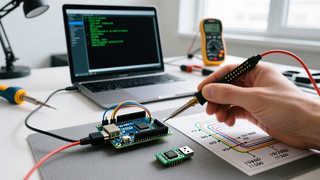

The Anatomy of the Arduino Serial Port in 2026
When makers and engineers refer to the 'Arduino serial port,' they are usually talking about a confluence of two distinct technologies: the hardware Universal Asynchronous Receiver-Transmitter (UART) native to the microcontroller, and the USB-to-Serial bridge that allows your modern PC to communicate with it. Understanding the boundary between these two layers is the difference between a smoothly uploading sketch and hours spent troubleshooting 'Port Not Found' errors in the IDE.
Unlike the legacy RS-232 DB9 serial ports of the 1990s, which operated at ±12V, the Arduino serial port operates at TTL (Transistor-Transistor Logic) levels—typically 0V for logic LOW and 5V (or 3.3V on newer boards) for logic HIGH. Connecting a raw 5V TTL UART pin directly to a legacy RS-232 port will instantly destroy the microcontroller. According to the SparkFun Serial Communication Guide, serial communication relies on asynchronous timing, meaning there is no shared clock line between the transmitter and receiver. Both devices must agree on a baud rate beforehand to sample the data line correctly.
Hardware Bridge vs. Native USB: Board-by-Board Breakdown
Not all Arduino serial ports are created equal. The architecture of the serial interface depends entirely on the specific board revision and microcontroller family you are using.
- Arduino Uno R3 (ATmega328P + ATmega16U2): The classic Uno uses a dedicated secondary microcontroller (the ATmega16U2) acting as a USB-to-Serial bridge. The main ATmega328P communicates with this bridge via hardware UART pins 0 (RX) and 1 (TX).
- Arduino Leonardo / Micro (ATmega32U4): These boards feature native USB. The main microcontroller handles USB communication directly. Consequently, the hardware UART on pins 0 and 1 is completely free to communicate with external sensors (like GPS modules) while the USB connection simultaneously handles Serial Monitor debugging via a virtual COM port.
- Arduino Uno R4 Minima (Renesas RA4M1): As detailed in the official Uno R4 Minima Cheat Sheet, the 32-bit Renesas chip handles native USB CDC (Communication Device Class) natively, eliminating the need for a bridge IC and allowing for vastly higher serial throughput and native HID keyboard/mouse emulation.
- Clone Boards (Nano/Uno with CH340G): To cut costs, third-party manufacturers replace the ATmega16U2 with the CH340G USB-to-Serial IC. While functionally identical for standard serial tasks, the CH340G requires specific drivers on older operating systems, though Windows 11 and modern macOS distributions now include native CH340 drivers out of the box.
Serial Architecture Comparison Matrix
| Board Model | Primary MCU | USB Bridge IC | Hardware UART Pins | Virtual COM Ports |
|---|---|---|---|---|
| Uno R3 | ATmega328P | ATmega16U2 | 0 (RX), 1 (TX) | 1 (Shared) |
| Mega 2560 | ATmega2560 | ATmega16U2 | 4 pairs (Serial, Serial1-3) | 1 (Shared with Serial) |
| Leonardo | ATmega32U4 | Native USB | 0 (RX1), 1 (TX1) | 1 (Independent) |
| Uno R4 Minima | Renesas RA4M1 | Native USB | Multiple configurable | 1 (Independent) |
The Mathematics of Baud Rates and Clock Drift
A common mistake in advanced MCU programming is assuming that any baud rate entered into Serial.begin() is perfectly accurate. Because the UART hardware generates timing by dividing the system clock, fractional remainders result in timing errors. For a standard 16 MHz Arduino Uno, the UART baud rate register (UBRR) is calculated as:
UBRR = (F_CPU / (16 * BAUD)) - 1
Let us look at the real-world math for common baud rates on a 16 MHz crystal:
- 9600 Baud: UBRR calculates to 103.16. The hardware rounds to 103. The actual baud rate becomes 9615 bps. Error: +0.16% (Perfectly safe).
- 115200 Baud: UBRR calculates to 7.68. The hardware rounds to 8. The actual baud rate becomes 111,111 bps. Error: -3.55%. While most modern UART receivers can tolerate up to a ±5% drift, chaining multiple logic level shifters or using long cables can cause bit errors at this speed.
- 250000 Baud: UBRR calculates to exactly 3.0. Error: 0.00%.
Expert Tip: If you are designing a high-speed data logging system pushing raw sensor arrays to a Python script on a PC, abandon 115200. Use 250000 or 500000 baud on a 16 MHz AVR board to achieve mathematically perfect clock division and eliminate timing-induced packet corruption.
The Auto-Reset Quirk: Capacitors and DTR Lines
Every time you open the Serial Monitor in the Arduino IDE, the board resets. This is not a bug; it is a deliberate hardware feature. The USB-to-Serial bridge asserts the DTR (Data Terminal Ready) line, which is routed through a 0.1µF capacitor to the microcontroller's RESET pin. This capacitor creates a brief low-voltage spike, triggering a reset so the bootloader can catch incoming firmware uploads.
However, if you are using the Arduino serial port to continuously stream data to a Raspberry Pi or a PC-based dashboard, opening the receiving terminal will reset the Arduino, interrupting your data flow. You can defeat this auto-reset behavior using one of two hardware modifications:
- The Capacitor Method: Solder a 10µF electrolytic capacitor between the RESET pin and the 5V pin. This absorbs the DTR spike, preventing the voltage from dropping low enough to trigger a reset.
- The Resistor Method: Place a 120-ohm resistor between the 5V and RESET pins. This overpowers the internal pull-down resistor triggered by the DTR line. (Note: You must remove this resistor when uploading new sketches via the IDE).
Expanding the Port: TTL to RS-485 Gateways
The native TTL serial port on pins 0 and 1 is highly susceptible to electromagnetic interference (EMI) and voltage drop. According to standard UART specifications, reliable TTL communication is limited to roughly 15 centimeters at high baud rates, or perhaps 2 meters at 9600 baud if heavily shielded.
For industrial environments, greenhouse automation, or multi-node sensor networks spanning hundreds of meters, you must convert the Arduino serial port to RS-485. By using a MAX485 or SP3485 transceiver IC (costing roughly $0.50 to $1.20 per unit in DIP-8 packages), you convert the single-ended TTL signal into a differential signal across two wires (A and B).
Differential signaling means the receiver reads the voltage difference between wire A and wire B, rather than comparing a single wire to ground. This provides immense common-mode noise rejection. An RS-485 bus driven by an Arduino can reliably span up to 1,200 meters at lower baud rates. Remember to place 120-ohm termination resistors at the extreme physical ends of the RS-485 bus to prevent signal reflection.
Real-World Troubleshooting: Serial Port Failures
Even in 2026, serial port issues remain the most common roadblock for embedded developers. Here is how to resolve the most persistent edge cases:
1. The 'Port Grayed Out' or 'Board Not Found' Error
If the IDE cannot see the port, the USB-to-Serial bridge has failed to enumerate. On clone boards, this is almost always a CH340 driver issue. Open your OS Device Manager (Windows) or System Information (macOS). If you see 'Unknown USB Device' or 'USB2.0-Serial' with a yellow warning triangle, you are missing the CH340 driver. Download the latest signed driver from the manufacturer. If the board is an official Uno R3 and fails to enumerate, the ATmega16U2 firmware may be corrupted. You can revive it using the 'Arduino UNO R3 Firmware Update' tool provided in the Arduino IDE installation folder under hardware/arduino/avr/firmwares/atmegaxxu2.
2. Gibberish Characters in the Serial Monitor
If your Serial Monitor outputs random symbols instead of text, your baud rates do not match. Ensure the dropdown menu in the bottom right corner of the IDE Serial Monitor exactly matches the integer inside your Serial.begin(9600); function. A secondary cause is clock drift on cheap clone boards. Some ultra-cheap Nanos use poorly calibrated internal oscillators or off-spec 16MHz crystals that drift more than 5%, causing bit errors at 115200 baud. Drop the baud rate to 9600 or 38400 to widen the receiver's sampling tolerance window.
3. Upload Timeouts ('Programmer is not responding')
This occurs when the IDE sends the upload command, but the bootloader fails to intercept it. This is often caused by external circuitry connected to pins 0 (RX) and 1 (TX). If you have a sensor, Bluetooth module, or wiring connected to the hardware UART pins, it can interfere with the DTR reset pulse or pull the RX line high, preventing the bootloader from receiving the firmware handshake. Always disconnect external devices from pins 0 and 1 before uploading code.
For a complete syntax reference on serial functions, including Serial.available(), Serial.readBytes(), and event-driven serial parsing, consult the Official Arduino Serial Language Reference. Mastering the physical and logical layers of the serial port transforms it from a simple debugging tool into a robust, high-speed backbone for complex embedded systems.