
The Bottlenecks in Remote Control Arduino Prototyping
Building a reliable remote control Arduino system is rarely as simple as wiring a transmitter to a receiver and uploading a sketch. Makers frequently encounter severe workflow bottlenecks during the integration phase: unexplained latency, dropped packets, voltage sags resetting the microcontroller, and blocking code that ruins real-time responsiveness. In 2026, with the maker market saturated with cheap clones and highly integrated SoCs like the ESP32-C3, optimizing your development workflow is the difference between a frustrating weekend project and a robust, deployable remote system.
This guide focuses strictly on workflow optimization for remote control builds. We will bypass basic wiring tutorials and dive into hardware debugging architectures, non-blocking software patterns, and RF edge-case mitigation that professional embedded engineers use to accelerate prototyping.
Module Selection Matrix: Matching Protocol to Workflow
Choosing the wrong communication protocol for your specific use case is the primary cause of project abandonment. Below is a decision matrix comparing the most common remote control modules available to makers, evaluated by workflow friction and real-world performance.
| Module / Protocol | Typical Cost (2026) | Max Range (LOS) | Workflow Friction | Best Use Case |
|---|---|---|---|---|
| TSOP38238 (38kHz IR) | $0.80 | 10 - 15m | Low (Line of sight required) | Indoor media centers, simple robotics |
| MX-FS-03V / SYN115 (433MHz ASK) | $1.50 (pair) | 30m (w/ antenna) | Medium (High noise floor, requires encoding) | Garage doors, simple telemetry, weather stations |
| nRF24L01+ PA/LNA (2.4GHz) | $4.50 | 800m | High (SPI tuning, power decoupling critical) | RC cars, drones, low-latency gaming controllers |
| HC-12 (433MHz UART) | $5.00 | 1000m | Low (AT commands, serial passthrough) | Long-range telemetry, agricultural sensors |
| ESP32-C3 (BLE 5.0 / Wi-Fi) | $3.50 | 50m (BLE) / 100m (Wi-Fi) | Medium (Requires network stack management) | Smart home integration, mobile app control |
Optimizing the Hardware Debugging Workflow
The 'Sniffer Node' Architecture
The most common mistake makers make is attempting to debug the remote control logic while simultaneously debugging the end-effector (e.g., motor drivers, servos, or relays). This conflates RF issues with mechanical or power issues.
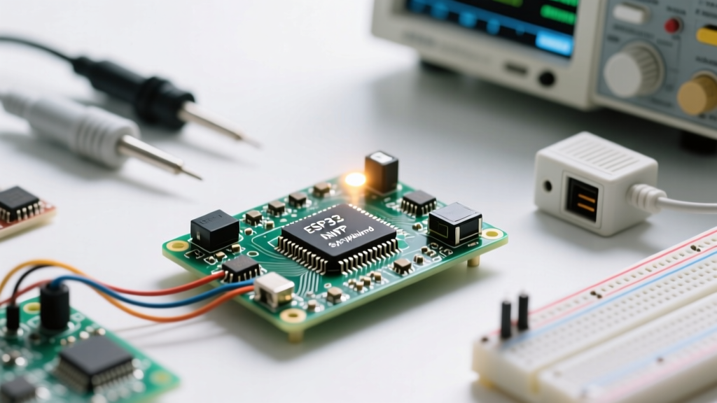
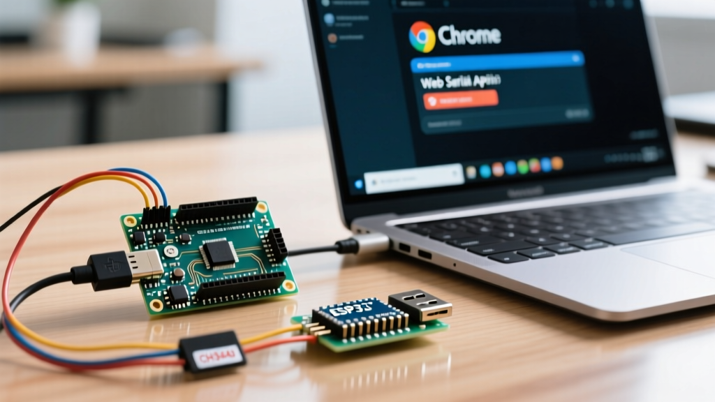
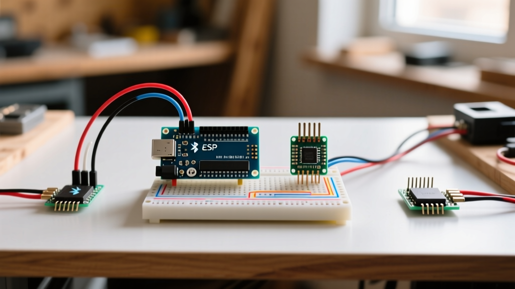
Workflow Optimization: Before integrating the receiver into your final robot or vehicle, build a dedicated 'Sniffer Node'. This is a standalone Arduino Nano or ESP32 wired solely to the receiver module and a serial-to-USB bridge. Write a minimal sketch that dumps raw hex payloads or pulse timings directly to the Serial Monitor at 115200 baud. By isolating the RF link, you can verify packet integrity, measure latency with an oscilloscope, and test range without the noise of motor PWM interference.
Bypassing the Blind Upload Problem
When working with modules like the HC-12 or raw 433MHz receivers, pin conflicts often prevent serial debugging. If your receiver is on the hardware UART pins (D0/D1 on an Uno), you cannot use the Serial Monitor while the module is active. Optimize your workflow by utilizing SoftwareSerial on alternative pins (e.g., D8/D9) for the RF module during the prototyping phase, reserving the hardware UART strictly for PC debugging. Once the logic is proven, migrate to hardware UART for production to reduce CPU overhead.
Power Management Edge Cases in Remote Nodes
Remote control receivers, particularly the nRF24L01+ and ESP32 variants, are notorious for causing microcontroller brownouts. The nRF24L01+ draws peak currents of up to 115mA during transmission bursts, while the ESP32 can spike over 250mA during Wi-Fi TX. The onboard 3.3V LDO of a standard Arduino Nano clone (often an AMS1117 rated for 800mA but poorly heat-sunk) will sag under these transient loads, causing the MCU to reset or the radio to drop off the SPI bus.
Expert Hardware Rule: Never power an nRF24L01+ directly from the 3.3V pin of a 5V Arduino board without decoupling. Solder a 10µF to 100µF ceramic or tantalum capacitor directly across the VCC and GND pins of the radio module. For high-power PA/LNA variants, use a dedicated 3.3V buck converter (like the MP1584EN) powered from the Arduino's 5V or VIN pin.
For battery-operated remote nodes, optimizing the sleep workflow is critical. According to the Espressif Deep Sleep Documentation, utilizing Wake-on-Radio (WOR) or external interrupt wake-ups via a low-power 433MHz receiver can extend battery life from days to months. Configure your main MCU to sleep and use a secondary, ultra-low-power MCU (like an ATtiny85 drawing 5µA) to listen for a specific RF wake-up sequence, which then triggers an interrupt to wake the primary controller.
Software Architecture: Non-Blocking State Machines
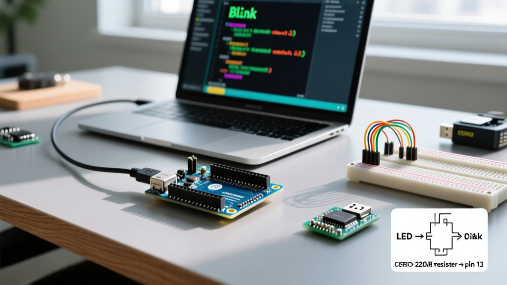
A remote control system must react to user inputs in under 50ms to feel responsive. Using delay() in your receiver sketch to debounce buttons or wait for motor timeouts will result in dropped packets and sluggish control. The Arduino BlinkWithoutDelay paradigm is mandatory for remote control workflows.
Implementing a Polling State Machine
Instead of linear code, structure your receiver loop as a finite state machine (FSM) driven by millis() timestamps. This ensures the RF payload is checked on every single loop iteration.
- State 0 (Idle): Check RF buffer. If payload received, parse and transition to State 1.
- State 1 (Actuate): Apply PWM to motors. Record
unsigned long startTime = millis();. Transition to State 2. - State 2 (Timeout Watch): Continuously check RF buffer. If new payload arrives, update PWM. If
millis() - startTime > 200(failsafe timeout), cut motor power and return to State 0.
This architecture guarantees that a lost packet results in an automatic, safe stop within 200ms, a critical safety requirement for remote control vehicles and machinery.
Antenna Tuning and Range Validation
Many makers blame the RF module for poor range when the actual failure point is the antenna. For 433MHz ASK modules (like the MX-FS-03V), the included spring antenna is often poorly matched. Optimize your range by soldering a straight, rigid wire exactly 17.3cm long (the quarter-wavelength for 433MHz in free space) to the ANT pad. For 2.4GHz nRF24L01+ modules, the quarter-wavelength is roughly 3.1cm.
Workflow Tip for Range Testing: Do not test range by walking away with the transmitter and waiting for the receiver to fail. Instead, use a programmable RSSI (Received Signal Strength Indicator) logger. The RF24 library allows you to read the RSSI register on compatible modules. Log the RSSI value to an SD card or an OLED display as you walk the perimeter of your testing area. This provides a quantitative heat map of dead zones caused by multipath fading and structural interference, allowing you to optimize antenna placement rather than guessing.
Expert Troubleshooting: Common Failure Modes
When your remote control Arduino build fails, use this diagnostic checklist before rewriting your code:
- SPI Bus Contention: If sharing the SPI bus with an SD card or OLED display, ensure the CS (Chip Select) pins are explicitly pulled HIGH when not in use. A floating CS pin will corrupt nRF24L01+ registers.
- Multipath Fading: If your 2.4GHz link drops at specific distances but works when closer or further, you are experiencing multipath phase cancellation. Move the receiver antenna 6cm in any direction to break the standing wave.
- Address Mismatch: In the RF24 library, ensure the pipe addresses are exactly 5 bytes long (e.g.,
0xF0F0F0F0E1LL). Using 4-byte integers will cause silent compilation errors and total link failure. - Ground Loops: When powering the transmitter from a PC USB and the receiver from a bench supply, ensure a common ground is established if using wired testing setups, though wireless isolation is preferred.
References & Further Reading
To deepen your understanding of RF protocols and embedded workflows, consult the following authoritative resources:
- SparkFun nRF24L01+ Transceiver Hookup Guide - Comprehensive wiring and library setup for 2.4GHz networks.
- Arduino BlinkWithoutDelay Documentation - The foundational guide to non-blocking timing in C++.
- Espressif ESP-IDF Sleep Modes API - Advanced power management for BLE and Wi-Fi remote nodes.