
The Bottlenecks in Traditional Fan Control Workflows
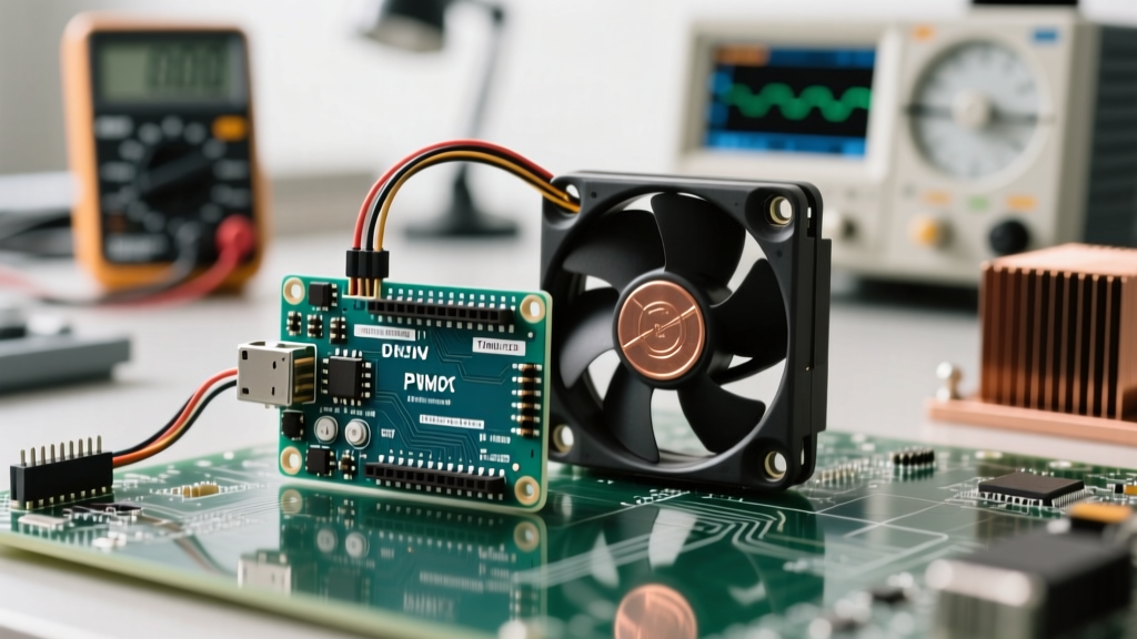
When makers and engineers first attempt to build a custom pwm control fan system using an Arduino or similar microcontroller, they inevitably hit the same three workflow bottlenecks: audible motor whine, melted breadboard traces, and erratic thermal feedback loops. These issues rarely stem from a lack of coding ability, but rather from a fundamental mismatch between standard microcontroller output behaviors and the strict electrical requirements of modern 4-wire PC and industrial fans.
Optimizing your workflow means front-loading the hardware and timer configurations so you can spend your time tuning thermal algorithms rather than debugging hardware failures. According to the Noctua PWM specifications white paper, modern 4-wire fans require a Pulse Width Modulation frequency between 21kHz and 28kHz to operate silently and efficiently. The default Arduino analogWrite() function operates at roughly 490Hz (or 980Hz on certain pins), which forces the fan's internal commutation electronics to audibly vibrate at that low frequency. By standardizing your workflow to address the 25kHz requirement immediately, you eliminate the most common point of failure in DIY cooling projects.
Hardware Selection: Bypassing the 5V Logic Trap
A critical workflow optimization is selecting the correct switching component to bridge the Arduino's 5V logic with the fan's 12V (or 24V) power rail. Directly driving a fan from an MCU pin will destroy the microcontroller. Furthermore, using the wrong transistor will lead to slow gate-switching times at high PWM frequencies, resulting in massive heat dissipation at the MOSFET.
Logic-Level MOSFETs vs. Dedicated Gate Drivers
Many beginners default to the IRLZ44N logic-level MOSFET. While it works for low-frequency applications, its high gate capacitance makes it a poor choice for 25kHz PWM control without a dedicated gate driver. At 25kHz, the Arduino pin cannot source enough current to charge the gate quickly, causing the MOSFET to linger in the linear (high-resistance) region and overheat.
| Component | Type | Key Spec (RDS/Drive) | Max Practical Freq | Workflow Verdict |
|---|---|---|---|---|
| IRLZ44N | N-Channel MOSFET | 0.022Ω @ 5V Vgs | < 1kHz | Avoid for 25kHz PWM; requires external driver. |
| TC4427 | MOSFET Driver IC | 1.5A Peak Sink/Source | > 100kHz | Excellent for driving large MOSFET gates at 25kHz. |
| BTS11C | Smart Low-Side Switch | 65mΩ RDS(on) | > 20kHz | Best overall; features built-in thermal shutdown and flyback clamping. |
Workflow Tip: Standardize your BOM (Bill of Materials) around Smart Low-Side switches like the BTS11C or BTS50080. These ICs include internal flyback diodes to handle the inductive kickback from the fan's motor coils, saving you the tedious step of wiring external 1N4148 diodes across every fan header on your custom PCB or perfboard.
Optimizing the Timer Configuration for 25kHz PWM
To achieve the Intel 4-wire fan specification of ~25kHz, you must bypass the standard Arduino wiring library and manipulate the hardware timers directly. On the ATmega328P (Arduino Uno/Nano), Timer2 controls pins 3 and 11. By adjusting the prescaler bits in the TCCR2B register, you can push the PWM frequency into the ultrasonic range, completely eliminating acoustic noise.
Insert this single line of code into your setup() function before calling any analogWrite() commands:
// Set Timer2 to 31.25kHz (Phase Correct PWM)
TCCR2B = TCCR2B & B11111000 | B00000001;
This register manipulation changes the prescaler to 1, resulting in a 31.25kHz signal. As detailed in Nick Gammon's definitive guide to Arduino timers, altering Timer2 will affect the millis() and delay() functions if you were modifying Timer0, but Timer2 is generally safe to alter for PWM purposes without breaking core Arduino timing functions. This single line of code is the highest-ROI workflow optimization you can implement for silent fan control.
Closed-Loop Thermal Feedback: Automating the Duty Cycle
Once the hardware is switching cleanly and the PWM signal is ultrasonic, the workflow shifts to software: mapping temperature sensor data to fan speed. Relying on simple if/else thresholds creates a jarring user experience where the fan rapidly ramps up and down (hysteresis oscillation).
Hysteresis vs. PID Control Algorithms
For low-thermal-mass environments (like cooling a small stepper motor driver or an enclosed Raspberry Pi), a basic hysteresis loop will cause the fan to 'hunt' around the target temperature. Implementing a PID (Proportional-Integral-Derivative) controller ensures smooth, asymptotic ramping.
"When tuning a PID loop for a pwm control fan, the derivative term (Kd) is often your worst enemy. Fan inertia and thermal lag create noisy derivative calculations, leading to erratic duty cycle spikes. For 90% of maker cooling applications, a well-tuned PI (Proportional-Integral) controller with a deadband provides superior stability compared to full PID."
Workflow Optimization: Do not hardcode your PI tuning values and repeatedly re-flash the MCU. Instead, utilize the Arduino Serial Plotter. Output your current temperature, target temperature, and raw duty cycle as comma-separated values. This allows you to adjust Kp and Ki variables via serial commands in real-time, visually observing the fan's response curve on your monitor. This cuts tuning time from hours to minutes.
Handling the Tachometer (RPM) Signal Without Blocking
A true 4-wire fan includes a yellow tachometer wire that outputs two square-wave pulses per revolution. Reading this signal is vital for confirming the fan hasn't stalled, but using pulseIn() or polling digitalRead() in your main loop will block your thermal sensing and PID calculations.
To optimize your workflow, use hardware interrupts. Wire the tachometer line to Arduino Pin 2 (Interrupt 0) with a 10kΩ pull-up resistor to 5V. The fan's internal open-collector transistor will pull the line to ground on each pulse.
volatile unsigned long pulseCount = 0;

void setup() {
  pinMode(2, INPUT_PULLUP);
  attachInterrupt(digitalPinToInterrupt(2), countPulse, FALLING);
}

void countPulse() {
  pulseCount++;
}

// In your main loop, calculate RPM every 1 second:
// RPM = (pulseCount / 2) * 60;
By offloading the pulse counting to the hardware interrupt vector, your main loop remains entirely free to handle I2C temperature sensors (like the BME280) and execute the PI control algorithm without missing a single fan revolution.
Troubleshooting Common PWM Signal Degradation
Even with an optimized workflow, environmental factors can degrade your pwm control fan setup. Use this structured checklist to diagnose issues rapidly without resorting to an oscilloscope:
- Fan Whines at Low Duty Cycles: Your PWM frequency has dropped below 20kHz. Verify that no other libraries (like Servo or IRremote) have hijacked Timer2 and overwritten your prescaler bits.
- Fan Stalls at 20% Duty Cycle: Many PC fans require a minimum 'kickstart' duty cycle to overcome static friction. Implement a software workaround: if the target duty cycle is below 30%, command 100% for 200 milliseconds before dropping to the target value.
- MCU Resets Randomly: Inductive kickback from the fan motor is back-feeding into your 5V rail. Ensure you are using a smart low-side switch with internal clamping, or add a Schottky diode (like the 1N5819) across the fan's power terminals.
- Erratic RPM Readings: The tachometer wire is acting as an antenna, picking up EMI from the PWM switching. Route the tachometer wire away from the MOSFET drain and ensure your 10kΩ pull-up resistor is physically close to the Arduino pin.
Conclusion: Standardizing Your Maker Workflow
Building a reliable, silent, and responsive pwm control fan system is less about writing complex code and more about respecting the electrical realities of brushless DC motors. By standardizing your hardware around smart low-side switches, forcing Timer2 into the 31kHz ultrasonic range, and utilizing hardware interrupts for tachometer feedback, you eliminate the most time-consuming debugging phases of thermal management. For further reading on signal modulation basics, refer to the SparkFun PWM Tutorial. Implement these structural optimizations in your next project, and you will spend less time troubleshooting hardware anomalies and more time perfecting your thermal algorithms.