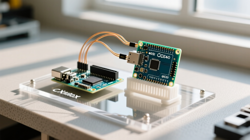

The Architectural Divide: Sequential vs. Parallel Execution
When makers first encounter the term Arduino FPGA, they often assume it refers to a single, magical chip that does everything. In reality, combining an Arduino (a microcontroller unit, or MCU) with a Field Programmable Gate Array (FPGA) is an exercise in hybrid architecture. To understand why you would pair them, you must first understand their fundamental architectural divide.
An Arduino, whether it is an Uno (ATmega328P) or a Portenta H7 (STM32H747), executes instructions sequentially. It fetches an instruction from flash memory, decodes it, executes it, and moves to the next. Even with high clock speeds (e.g., 480 MHz on the Portenta), the MCU is fundamentally bound by its instruction pipeline and interrupt latency.
An FPGA, conversely, is not a processor. It is a blank canvas of configurable logic blocks (CLBs), flip-flops, and programmable interconnects. When you program an FPGA, you are not writing software; you are physically wiring digital hardware. This allows for true parallel execution. According to Nandland FPGA Fundamentals, an FPGA can process hundreds of video pixels or ADC samples simultaneously in a single clock cycle, a feat impossible for a sequential MCU.
The Golden Rule of Hybrid Design: Use the Arduino for high-level decision making, user interfaces, and network communication. Offload high-speed, deterministic, parallel data processing to the FPGA.
Bridging the Gap: How Arduino and FPGA Communicate
In an Arduino FPGA setup, the MCU typically acts as the "master" or system controller, while the FPGA acts as a hardware coprocessor or custom peripheral. They communicate via standard serial protocols, most commonly SPI (Serial Peripheral Interface) or I2C.
The SPI Bottleneck and Signal Integrity
SPI is the preferred bus for MCU-FPGA communication due to its speed. However, integrating them requires strict attention to signal integrity. An Arduino Nano RP2040 Connect can theoretically push its SPI clock to 30 MHz or higher. But pushing 30 MHz square waves across standard 2.54mm breadboard jumper wires will result in severe signal reflection, ringing, and data corruption.
- Under 10 MHz: Standard jumper wires and breadboards are generally sufficient for prototyping.
- 10 MHz to 25 MHz: You must use short, twisted-pair wiring or a custom PCB with controlled impedance. Ground return paths must be directly adjacent to signal lines.
- Above 25 MHz: You must transition to a dedicated PCB or high-speed board-to-board mezzanine connectors. At this point, you should consider parallel buses or LVDS (Low-Voltage Differential Signaling) instead of single-ended SPI.
Hardware Ecosystem: Arduino FPGA Boards in 2026
The landscape of hybrid boards has evolved significantly. Here are the primary ways makers integrate these technologies today:
1. The All-in-One: Arduino MKR Vidor 4000
The Arduino MKR Vidor 4000 remains a benchmark for integrated hybrid design. It pairs a Microchip SAMD21 (ARM Cortex-M0+) with an Intel Cyclone 10LP FPGA (16K Logic Elements). The SAMD21 handles the Arduino IDE environment and USB communication, while the Cyclone 10LP handles tasks like HDMI video encoding or high-speed DSP. While powerful, its proprietary toolchain integration can be restrictive for advanced users wanting raw Verilog access.
2. The Modern Open-Source Approach: Arduino + Lattice ECP5
In 2026, the most popular approach among advanced makers is pairing a standard Arduino (like the Nano ESP32 or Portenta) with a standalone Lattice ECP5 breakout board, such as the OrangeCrab or ULX3S. The ECP5 family is fully supported by the open-source Yosys and nextpnr toolchains, freeing developers from the multi-gigabyte proprietary suites of Intel (Quartus) or AMD/Xilinx (Vivado). The Arduino manages the Wi-Fi/BLE stack, streaming data over SPI to the ECP5 for real-time cryptographic hashing or motor control.
Comparison Matrix: MCU, FPGA, and Hybrid Setups
| Feature | Pure Arduino (e.g., Uno R4) | Pure FPGA (e.g., Alchitry Au) | Hybrid (Arduino + FPGA) |
|---|---|---|---|
| Execution Model | Sequential (Software) | Parallel (Hardware) | Both (Partitioned) |
| Boot Time | Instant (Milliseconds) | Slow (Flash config load) | Staged (MCU boots, then configures FPGA) |
| Peripheral Ecosystem | Massive (Shields, Libraries) | Minimal (Requires custom IP cores) | High (MCU handles complex I/O like USB/Wi-Fi) |
| Development Curve | Low (C++ / Arduino API) | High (Verilog/VHDL, Timing Closure) | Very High (Requires both skill sets + bus debugging) |
| Typical Cost (2026) | $15 - $30 | $60 - $150+ | $40 - $120 (Combined) |
Critical Failure Modes and Wiring Rules
Integrating an Arduino with an FPGA is fraught with hardware pitfalls. The most common failure mode is not a software bug, but a fried I/O bank. Follow these strict wiring rules to protect your hardware:
- Logic Level Mismatch: Most modern FPGAs operate at 1.8V or 3.3V logic levels. The classic Arduino Uno outputs 5V. Connecting a 5V Arduino SPI pin directly to a 3.3V FPGA input will permanently destroy the FPGA's I/O clamp diodes. Always use a bidirectional logic level shifter, such as the Texas Instruments SN74LVC8T245 or the SparkFun Logic Level Converter.
- The MISO Tri-State Problem: If your FPGA shares the SPI bus with other sensors, the FPGA's MISO (Master In Slave Out) pin must be configured as a tri-state buffer in your Verilog/VHDL code. If the FPGA continuously drives the MISO line high or low while another sensor is trying to talk to the Arduino, you will create a short circuit on the data bus.
- Configuration Pin Strapping: Many FPGAs use their I/O pins for configuration strapping during boot. If the Arduino is driving these pins before the FPGA has finished loading its bitstream, the FPGA may boot into the wrong mode (e.g., Slave Serial instead of Master SPI). Use series resistors (33 to 100 ohms) on shared lines to prevent back-powering and boot conflicts.
Frequently Asked Questions
Can I program the FPGA directly using the Arduino IDE?
Generally, no. The Arduino IDE compiles C/C++ code for microcontrollers. FPGAs require Hardware Description Languages (HDLs) like Verilog, VHDL, or Amaranth, compiled via specialized toolchains (Vivado, Quartus, or Yosys). However, in integrated boards like the MKR Vidor 4000, the Arduino IDE can load pre-compiled FPGA bitstreams (IP blocks) via specialized libraries, abstracting the HDL away from the user.
Is an FPGA overkill for reading a fast encoder?
It depends on the speed and count. If you are reading a single 10 kHz quadrature encoder, an Arduino's hardware interrupts are perfectly adequate. If you are reading six 50 kHz encoders simultaneously for a hexapod robot while calculating inverse kinematics, an FPGA is necessary to capture the counts deterministically without dropping pulses due to MCU interrupt latency.
How does the Arduino load the bitstream into the FPGA?
In most hybrid setups, the FPGA's configuration flash is programmed via a dedicated JTAG or USB-to-UART programmer during development. In production or advanced field-updatable designs, the Arduino can act as a "Master Serial" configuration controller, pushing the bitstream file from its own SD card or flash memory into the FPGA's SRAM over SPI upon boot.