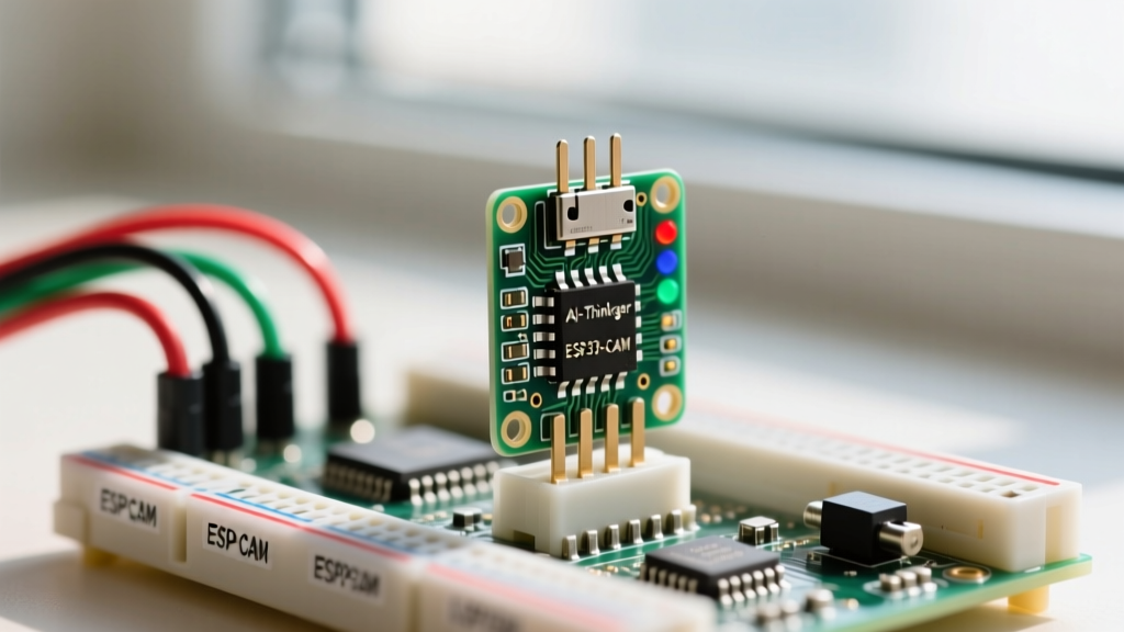

The AI-Thinker ESP32-CAM remains one of the most cost-effective entry points into embedded computer vision and IoT streaming. Priced typically between $6 and $9, it pairs a dual-core ESP32 SoC with an OV2640 2-megapixel sensor and 4MB of PSRAM. However, its compact footprint strips away standard amenities like a native USB port and robust voltage regulation, turning what should be a simple project into a frustrating exercise in hardware debugging for many makers.
This tutorial bypasses the generic advice and dives straight into the electrical realities, precise Arduino IDE configurations, and specific hardware traps you must navigate to successfully stream live video from your ESP32 camera module.
The Hardware Reality: AI-Thinker ESP32-CAM & OV2640
Before writing a single line of code, you must understand the physical limitations of the AI-Thinker board. The module utilizes the ESP32-S chip, which lacks the native USB-to-Serial bridge found on standard ESP32 DevKits. Furthermore, the board integrates an AMS1117-3.3 linear voltage regulator. This component is notoriously inefficient; when the ESP32 transmits Wi-Fi data while simultaneously compressing JPEG frames, current spikes can exceed 350mA. The AMS1117 will rapidly overheat and drop voltage if not fed a stable 5V source, leading to the infamous 'brownout' reboots.
The Antenna Resistor Trap
Out of the box, the ESP32-CAM routes its RF signal to the onboard PCB trace antenna. The board includes a U.FL (IPEX) connector for an external 2.4GHz antenna, but plugging it in does nothing by default. To route the signal to the external antenna, you must locate the 0-ohm surface-mount resistor (usually labeled R13 or R15 depending on the board revision) near the U.FL connector. Using a hot air station or a fine-tipped soldering iron, you must desolder this resistor and rotate it 90 degrees to bridge the external antenna pads. If you are operating the camera inside a metal enclosure or at the edge of your Wi-Fi router's range, this hardware modification is mandatory to prevent packet loss and stream freezing.
Pre-Flight Checklist: FTDI Wiring & Power Delivery
Because the ESP32-CAM lacks a USB port, you must use an external USB-to-TTL serial converter, such as the FT232RL FTDI adapter. A critical mistake made by beginners is powering the module via the FTDI's 3.3V pin. Most standard FTDI adapters can only source 50mA to 100mA on their 3.3V line, which is woefully inadequate for the ESP32-CAM.
Required Wiring Configuration:
- FTDI 5V to ESP32-CAM 5V (Bypasses the weak 3.3V FTDI regulator and uses the onboard AMS1117)
- FTDI GND to ESP32-CAM GND
- FTDI TX to ESP32-CAM U0R (RX)
- FTDI RX to ESP32-CAM U0T (TX)
- ESP32-CAM GPIO 0 to ESP32-CAM GND (Crucial for entering UART download mode)
Expert Power Tip: If your FTDI adapter cannot supply a clean 5V/1A output, bypass the FTDI power entirely. Connect the FTDI data lines (TX/RX/GND) to the ESP32-CAM, but power the ESP32-CAM's 5V and GND pins using a dedicated 5V 2A laboratory power supply or a high-quality USB wall wart breadboard adapter.
Arduino IDE Configuration: Avoiding the PSRAM Trap
The OV2640 sensor generates massive frame buffers. Without the 4MB PSRAM (pseudo-SRAM) enabled, the ESP32's 520KB internal SRAM will instantly overflow, causing a continuous reboot loop. The Arduino IDE must be explicitly told to compile for a chip with PSRAM.
- Open the Arduino IDE and navigate to File > Preferences. Add the Espressif board manager URL:
https://raw.githubusercontent.com/espressif/arduino-esp32/gh-pages/package_esp32_index.json. - Go to Tools > Board > Boards Manager, search for 'esp32', and install the latest stable version of the 'esp32 by Espressif Systems' package.
- Select Tools > Board > ESP32 Arduino > ESP32 Wrover Module. Do not select 'ESP32 Dev Module', as the default compiler flags for the Dev Module disable PSRAM access.
- Set Tools > Partition Scheme to Huge APP (3MB No OTA/1MB SPIFFS). The camera web server binary is large and requires the extra flash allocation.
- Ensure Tools > PSRAM is set to Enabled.
Flashing the CameraWebServer Sketch
The official ESP32 Arduino core includes a highly optimized example sketch for streaming. Navigate to File > Examples > ESP32 > Camera > CameraWebServer.
Modifying the Code for Your Network
Before compiling, you must make three critical modifications to the sketch:
- Uncomment the definition for the AI-Thinker board:
#define CAMERA_MODEL_AI_THINKER. Ensure all other camera model definitions remain commented out. - Enter your 2.4GHz Wi-Fi credentials in the
ssidandpasswordconstants. (Note: The ESP32 does not support 5GHz networks). - Verify the pin definitions match the AI-Thinker schematic. The default example code already contains the correct GPIO mappings for the AI-Thinker's XCLK, SIOD, SIOC, and data pins.
The Upload Sequence
With GPIO 0 tied to GND, click Upload in the Arduino IDE. Once the console displays 'Connecting...', press the RESET button on the back of the ESP32-CAM for one second and release it. This forces the bootloader to latch into download mode. After the upload reaches 100%, disconnect the GPIO 0 to GND jumper wire and press the RESET button one final time to boot into normal run mode.
Troubleshooting the 'Camera Init Failed' Error
Open the Serial Monitor at 115200 baud. If the stream fails to start, the ESP32 will output a specific hexadecimal error code. Understanding these codes separates guesswork from targeted hardware repair. For deeper architectural insights into the camera driver, refer to the official Espressif esp32-camera GitHub repository.
| Error Code | Meaning | Hardware / Software Fix |
|---|---|---|
0x20001 |
I2C Bus Timeout / Sensor Not Found | The ESP32 cannot find the OV2640 at I2C address 0x30. Reseat the delicate ribbon cable. Check for bent pins on the sensor connector. |
0x20002 |
PSRAM Initialization Failed | You selected the wrong board in the IDE. Switch to 'ESP32 Wrover Module' and ensure PSRAM is Enabled in the Tools menu. |
0x105 |
Out of Memory / Buffer Alloc Fail | Frame size is too large for available RAM. Lower the default frame size in the sketch from UXGA to SVGA or VGA for initial testing. |
Brownout |
Voltage Drop Below 2.4V | Your 5V source is sagging under load. Upgrade to a 5V 2A power supply and ensure you are using thick gauge wires for the 5V/GND connections. |
Optimizing the Stream: Frame Rates and Thermal Throttling
Once the web server is running, you can access the IP address printed in the Serial Monitor to view the stream interface. The default settings often prioritize resolution over framerate. For robotics or real-time tracking applications, navigate to the web interface settings and drop the resolution to CIF (400x296) or QVGA (320x240). This drastically reduces the JPEG compression load on the ESP32's CPU, pushing framerates from a sluggish 5 FPS up to 20+ FPS.
Finally, address thermal throttling. The ESP32 chip and the AMS1117 regulator will become hot to the touch during continuous streaming. While the ESP32 silicon is rated to operate at high temperatures, the surrounding passive components and the camera sensor itself suffer from thermal noise, resulting in a grainy, purple-tinted image. Affix a small 14x14x6mm aluminum heatsink with thermal tape directly to the ESP32 metal RF shield. This simple $0.50 addition stabilizes the internal voltage regulator and significantly improves long-term image quality.
For further reading on advanced implementations, including integrating face recognition and motion tracking with this exact hardware setup, the comprehensive guides at RandomNerdTutorials provide excellent supplementary code examples. Mastering the ESP32 camera requires respecting its power envelope and memory architecture, but once dialed in, it remains an unparalleled tool for IoT vision projects.