
The Evolution of Automotive Arduino Projects in 2026
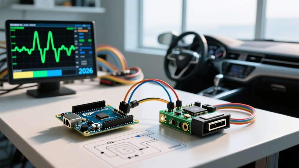
The intersection of maker culture and vehicle electronics has never been more vibrant. What started as simple OBD2 code readers built on Arduino Unos has evolved into complex, real-time telemetry systems, custom digital instrument clusters, and EV battery management integrations. As 2026 vehicle architectures increasingly rely on CAN FD (Flexible Data-Rate), Automotive Ethernet, and zoned domain controllers, the automotive Arduino community has had to adapt rapidly.
This roundup curates the most valuable community resources, open-source repositories, and hardware configurations vetted by automotive engineers and advanced makers. Whether you are reverse-engineering a CAN matrix or building a standalone data logger, these resources will bridge the gap between hobbyist microcontrollers and harsh automotive environments.
Core Hardware: Community-Approved Automotive Boards
The standard Arduino Uno is fundamentally unsuited for modern vehicle networks due to its 5V logic, lack of native CAN support, and limited processing overhead. The community has largely standardized around specific 3.3V, high-clock-speed alternatives that can handle the 8 Mbps throughput of CAN FD.
| Microcontroller Board | CAN Capability | Approx. Price (2026) | Best Automotive Use Case |
|---|---|---|---|
| Teensy 4.1 | Dual CAN 3.0 (FD capable) | $32.00 | High-speed data logging, custom gauge clusters |
| Arduino Portenta H7 | Native CAN FD, High-Speed I/O | $105.00 | Machine vision, complex ADAS prototyping |
| Macchina M2 | Dual CAN, LIN, J1939, OBD2 | $75.00 | Direct OBD2 port plugging, ECU reverse engineering |
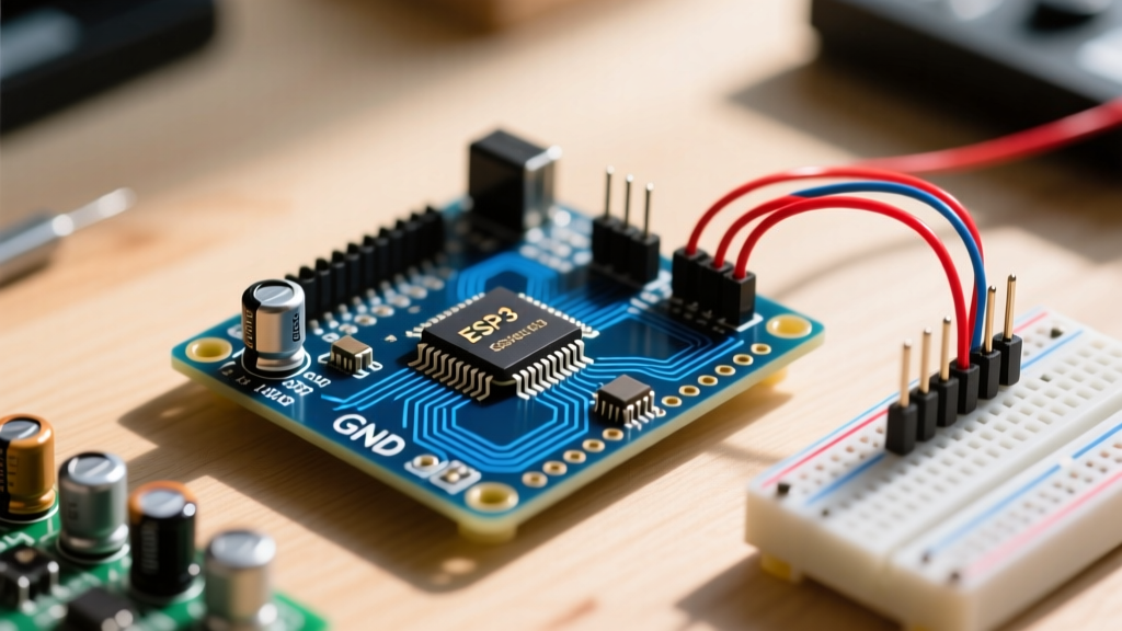
| ESP32-S3 (WROOM) | TWAI (CAN 2.0B compatible) | $8.00 | Wireless telemetry, Bluetooth OBD2 bridges |
For pure reverse engineering, the Macchina M2 remains a community darling. Its open-source hardware design includes built-in transceivers, a direct OBD2 connector footprint, and native support for LIN bus, making it a Swiss Army knife for vehicle diagnostics.
Power Supply Survival: Defeating the Load Dump
The most common point of failure in automotive Arduino builds is not software—it is power supply destruction. A vehicle's electrical system is notoriously hostile. While nominal voltage is 12V (or 24V in heavy trucks), alternator charging pushes this to 14.4V. More critically, a load dump—which occurs when a depleted battery is suddenly disconnected while the alternator is spinning—can send voltage spikes exceeding 60V for several hundred milliseconds.
The Community-Standard Protection Circuit
Do not rely on standard LM7805 linear regulators or cheap buck converters from online marketplaces. They lack the transient voltage suppression required for ISO 7637-2 compliance. The established automotive Arduino power topology includes:
- Reverse Polarity Protection: A P-channel MOSFET (e.g., IRF9540N) or an ideal diode controller to prevent damage if battery terminals are crossed.
- Transient Voltage Suppression (TVS):strong> A bidirectional TVS diode like the SMAJ33CA clamps load dump spikes safely to ground.
- Wide-Input DC-DC Converter: Switching regulators like the RECOM R-78E5-1.0 or Murata OKI-78SR-5/1.5-W36-C accept inputs up to 36V continuously and survive 60V transients when paired with a TVS diode.
Pro-Tip from the r/CarHacking Community: Always measure your vehicle's ground offset. In older vehicles, the chassis ground at the dashboard can differ from the battery negative terminal by up to 0.5V under heavy load. This ground loop can corrupt CAN bus differential signaling or fry your MCU's UART lines. Use isolated DC-DC converters (like the RECOM RO-0505S) for any datalines crossing between different vehicle zones.
Essential Open-Source Libraries and Software
Writing raw CAN register configurations is a rite of passage, but the community has developed robust abstraction layers that save hundreds of hours of debugging.
1. MCP_CAN_lib (The Legacy Workhorse)
Despite the rise of native CAN peripherals, the MCP2515 SPI-to-CAN controller remains ubiquitous in DIY projects due to its low cost (under $3 per module). The MCP_CAN_lib repository is the definitive community-maintained fork. It includes critical fixes for buffer overflows and supports custom baud rates required for proprietary networks (like Honda's 33.3 kbps B-CAN or Nissan's 500 kbps EV-CAN).
2. SavvyCAN (Reverse Engineering Matrix)
When you plug into a 2026 vehicle, you will be bombarded with thousands of CAN frames per second. SavvyCAN is an open-source, cross-platform CAN bus analysis tool heavily utilized by the EV conversion community. It allows you to capture traffic, perform bit-flow analysis, and automatically decode DBC files. Pairing SavvyCAN with a Teensy 4.1 running a pass-through sketch is the gold standard for mapping out unknown vehicle networks.
3. Comma.ai Openpilot CAN Dictionaries
While primarily an autonomous driving project, the comma.ai open-source repository contains one of the largest publicly available databases of CAN message definitions for modern vehicles. Makers frequently scrape their fingerprinting databases to find the exact CAN IDs for steering wheel angle, wheel speed, and brake pressure on late-model cars.
Physical Layer Troubleshooting: The 60-Ohm Rule
A frequent question in automotive Arduino forums revolves around intermittent CAN bus disconnects or 'bus-off' errors. 90% of these issues stem from improper physical layer termination.
- The 120-Ohm Standard: High-speed CAN (ISO 11898-2) requires a 120-ohm resistor at each end of the bus. When measured with a multimeter between CAN_H and CAN_L, the network should read exactly 60 ohms (two 120-ohm resistors in parallel).
- The 'Too Many Resistors' Edge Case: Many off-the-shelf MCP2515 transceiver boards come with a 120-ohm termination resistor pre-soldered (often labeled 'J1' or '120'). If you plug two of these into a network that already has OEM ECU termination resistors, your network impedance drops to 40 ohms or lower. This causes signal reflection and communication failure. Always check your transceiver boards with a continuity tester and desolder the jumper if necessary.
- Wiring Topology: CAN bus must be wired in a linear bus topology, not a star topology. Star wiring creates signal reflections at the junction points. Keep stub lengths (the wire from the main bus to your Arduino transceiver) under 30 centimeters to prevent high-frequency signal degradation, especially on CAN FD networks.
Where to Connect: Active Community Hubs
The best troubleshooting happens in real-time with peers who have encountered the same ECU quirks. Bookmark these community hubs:
- OpenVehicleMonitoringSystem (OVMS) Forums: While focused on their specific hardware, the OVMS forums contain decades of reverse-engineered CAN data for Tesla, Nissan Leaf, and Chevy Volt platforms.
- MACCHINA Discord: The premier gathering spot for automotive security researchers, ECU tuners, and hardware hackers. Excellent for getting help with UDS (Unified Diagnostic Services) protocol implementation.
- r/CarHacking & r/InstrumentCluster: Subreddits dedicated to modifying vehicle firmware, extracting EEPROM data, and building custom Arduino-driven gauge clusters.
Final Thoughts on Automotive Maker Ethics
As vehicles become more software-defined, the line between a harmless DIY telemetry project and critical safety system interference blurs. The community consensus for 2026 is strict: never transmit on safety-critical CAN buses (like airbag deployment or primary braking networks) unless you are operating in a controlled, off-road testing environment. Utilize the OBD2 port for read-only passive logging, or use hardware firewalls to isolate your Arduino projects from the vehicle's core safety domains. By leveraging these open-source resources and adhering to automotive-grade hardware practices, your builds will survive the harsh reality of the road.