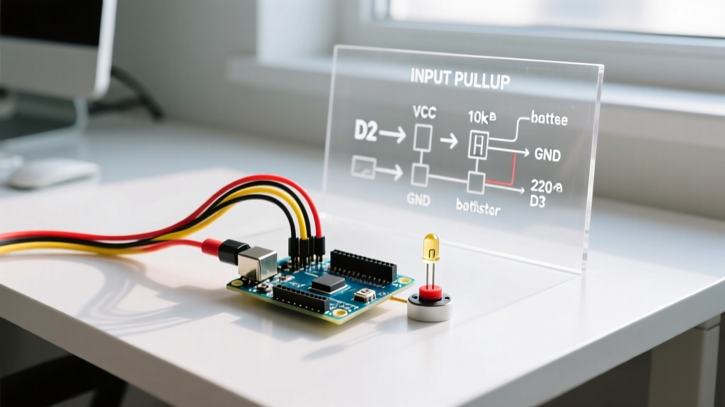

The Anatomy of a Reliable Arduino LED Button Circuit
Building an arduino led button circuit is universally recognized as the 'Hello World' of hardware electronics. However, while basic tutorials get an LED blinking, they frequently ignore the underlying electrical realities that cause circuits to fail in real-world applications. Floating pins, mechanical switch bounce, and voltage drops across long wire runs can turn a simple configuration into a frustrating debugging session.
This configuration guide moves beyond elementary breadboard sketches. We will cover the exact component mathematics, the physics of contact bounce, and the industry-standard software configurations required to build a robust, production-ready button interface for your microcontroller projects in 2026.
Hardware Configuration: Wiring and Component Math
A common beginner mistake is connecting an LED directly to an Arduino digital pin without a current-limiting resistor, or wiring a button without a pull-up/pull-down resistor. Let us define the exact electrical parameters for a standard 5V Arduino Uno R3 or compatible ATmega328P board.
LED Current Limiting Calculation
Standard 5mm through-hole LEDs typically have a forward voltage (Vf) of 2.0V (for red) to 3.2V (for blue/white) and a maximum continuous forward current (If) of 20mA. To calculate the required resistor using Ohm's Law:
R = (Vcc - Vf) / If
For a Red LED on a 5V rail: R = (5.0V - 2.0V) / 0.02A = 150Ω.
While 150Ω is the mathematical minimum, using a 220Ω or 330Ω 1/4W carbon film resistor is standard practice. This provides a safety margin that extends the LED lifespan and reduces the current draw on the ATmega328P's internal I/O pins, which are rated for an absolute maximum of 40mA per pin (with a recommended limit of 20mA).
Pin Mapping and Breadboard Layout
Instead of using an external 10kΩ pull-down resistor to ground, modern Arduino configuration relies on the microcontroller's internal pull-up resistors. According to the official Arduino PinMode reference, the ATmega328P features internal pull-up resistors in the range of 20kΩ to 50kΩ. This simplifies the wiring significantly.
| Component | Microcontroller Pin | Electrical State | Notes |
|---|---|---|---|
| Tactile Switch (Leg 1) | Digital Pin 2 | INPUT_PULLUP | Reads HIGH when open, LOW when pressed |
| Tactile Switch (Leg 2) | GND | Ground | Completes the circuit to ground |
| LED Anode (+) | Digital Pin 8 | OUTPUT | Connect via 220Ω resistor |
| LED Cathode (-) | GND | Ground | Shorter leg, flat edge on casing |
Choosing the Right Tactile Switch for 2026 Projects
Not all buttons are created equal. When sourcing components for your arduino led button setup, avoid unbranded bulk switches that suffer from oxidation and inconsistent actuation. Look for the C&K PTS645 series or the Omron B3F series. These switches offer:
- Actuation Force: Typically 160gf to 260gf, providing a crisp tactile snap.
- Lifecycle Rating: 100,000 to 1,000,000 cycles, ensuring the internal beryllium copper contacts do not fatigue prematurely.
- Low Contact Resistance: Under 100mΩ, ensuring clean logic-level transitions.
The Physics of Switch Bounce (And Why Your Code Fails)
If you have ever written a simple digitalRead() loop to toggle an LED, you likely noticed the LED behaving erratically, toggling multiple times for a single physical press. This is not a software bug; it is a mechanical reality.
When the metal contacts inside a tactile switch close, they do not make a single, clean connection. Instead, they physically bounce against each other for 1 to 5 milliseconds before settling. To a microcontroller executing millions of instructions per second, this bounce registers as dozens of rapid, distinct button presses. As detailed in the comprehensive Hackaday guide on switch debouncing, ignoring this physical characteristic will render any state-change logic completely unreliable.
Software Configuration: Debouncing with Bounce2
While you can write custom millis() timers to filter out bounce, the industry standard for Arduino environments is the Bounce2 library. It abstracts the timing math, handles edge detection (rising/falling), and ensures non-blocking execution.
Install the Bounce2 library via the Arduino IDE Library Manager, then upload the following optimized configuration sketch:
#include <Bounce2.h>

const int BUTTON_PIN = 2;
const int LED_PIN = 8;

Bounce debouncer = Bounce();
bool ledState = false;

void setup() {
  // Configure internal pull-up resistor
  pinMode(BUTTON_PIN, INPUT_PULLUP);
  pinMode(LED_PIN, OUTPUT);

  // Attach the debouncer to the pin with a 5ms interval
  debouncer.attach(BUTTON_PIN);
  debouncer.interval(5);

  digitalWrite(LED_PIN, LOW);
}

void loop() {
  // Update the debouncer state machine
  debouncer.update();

  // Detect the exact moment the button is pressed (Falling edge due to INPUT_PULLUP)
  if (debouncer.fell()) {
    ledState = !ledState;
    digitalWrite(LED_PIN, ledState);
  }
}
Configuration Note: Because we are using INPUT_PULLUP, the default state of the pin is HIGH (5V). Pressing the button connects the pin to GND, pulling it LOW. Therefore, we use debouncer.fell() to detect the press, rather than rose().
Advanced Edge Cases: Long Wires and EMI
If your arduino led button project requires the button to be mounted more than 1 meter away from the microcontroller (e.g., in an automotive dashboard or a large escape room prop), standard internal pull-ups will fail. Long wires act as antennas, picking up Electromagnetic Interference (EMI) and introducing parasitic capacitance that slows down the logic-level rise time.
The Long-Run Solution
- External Pull-Up: Disable the internal pull-up and solder a physical 4.7kΩ resistor between the 5V rail and the signal wire at the microcontroller end.
- Hardware Debounce (RC Filter): Solder a 100nF (0.1µF) ceramic capacitor directly across the two legs of the tactile switch. This creates a low-pass filter that physically absorbs the high-frequency bounce spikes before they ever reach the microcontroller pin.
- Twisted Pair: Run the signal wire and the ground wire as a twisted pair to cancel out induced magnetic noise from nearby motors or relays.
Troubleshooting Matrix
Use this diagnostic table when your circuit fails to behave as expected during testing.
| Symptom | Root Cause | Configuration Fix |
|---|---|---|
| LED toggles randomly without pressing button | Floating pin / EMI interference | Ensure INPUT_PULLUP is declared in setup(). Check for loose breadboard contacts. |
| LED toggles 3-4 times per single physical press | Mechanical switch bounce | Increase debouncer.interval() to 10ms or 15ms. Verify Bounce2 library is updating in loop(). |
| LED is extremely dim | Incorrect resistor value or pin sourcing limit | Verify resistor is ≤ 330Ω. Ensure LED is not being driven by a 3.3V pin on a 5V board. |
| Button works on USB power, fails on battery | Voltage drop / Insufficient current | Measure Vcc with a multimeter under load. Upgrade battery chemistry (e.g., from 9V alkaline to 4x AA NiMH). |
By respecting the electrical characteristics of your components and implementing robust software debouncing, your arduino led button configuration will transition from a fragile breadboard experiment to a reliable, deployment-ready interface.