
When building audio feedback loops for maker projects, the combination of a buzzer and Arduino remains one of the most reliable, cost-effective methods for generating alerts, melodies, and UI sounds. However, as the maker community has evolved through 2026, so too has our understanding of the hardware limitations, software conflicts, and best practices surrounding these simple piezoelectric and electromagnetic components. This community resource roundup curates the most valuable insights, wiring schematics, and library recommendations from top-tier forums, GitHub repositories, and expert publications to help you master buzzer integration without frying your microcontroller.
The Great Debate: Active vs. Passive Buzzers
The most frequent point of confusion for beginners navigating the Arduino Forum is the difference between active and passive buzzers. While they look nearly identical on the outside (often housed in the same black cylindrical casing with a small hole on top), their internal architecture and driving requirements are fundamentally different.
| Feature | Active Buzzer (e.g., KY-012 / TMB12A05) | Passive Buzzer (e.g., KY-006 / Piezo Disc) |
|---|---|---|
| Internal Oscillator | Yes (Built-in driving circuit) | No (Requires external AC/PWM signal) |
| Control Method | Simple DC Voltage (HIGH/LOW) | PWM / Square Wave (AC Signal) |
| Frequency Control | Fixed (Usually 2.3kHz - 2.7kHz) | Variable (Depends on input frequency) |
| Current Draw | ~30mA (Requires transistor driver) | <5mA (Can often be driven directly by GPIO) |
| Avg. Price (2026) | $0.15 - $0.25 per unit (Bulk) | $0.05 - $0.10 per unit (Bulk) |
| Best Use Case | Alarms, simple beeps, status alerts | Melodies, RTTTL songs, variable tones |
Community Consensus: If your project only requires a single, consistent alert tone (like a microwave beep or a smoke detector chirp), use an active buzzer. If you intend to play melodies, generate variable-frequency feedback, or use RTTTL (Ring Tone Text Transfer Language) files, a passive piezo buzzer is mandatory.
Hardware Protection: The Community-Approved Driver Circuit
A critical mistake documented repeatedly in community troubleshooting threads is connecting an active electromagnetic buzzer directly to an ATmega328P or ESP32 GPIO pin. Most standard 5V active buzzers draw between 30mA and 40mA. While an Arduino Uno pin can theoretically source up to 40mA absolute maximum, the recommended safe operating current is 20mA. Continuously pulling 35mA from a single GPIO pin will degrade the silicon over time, leading to permanent pin failure.
The NPN Transistor Driver Topology
To safely drive a buzzer and Arduino setup, the community standard is to use an NPN transistor as a low-side switch. Here is the exact bill of materials and wiring configuration recommended by experienced hardware engineers:
- Transistor: 2N3904 or 2N2222 (NPN BJT). Cost: ~$0.03 each.
- Base Resistor: 1kΩ resistor connected between the Arduino PWM/Digital pin and the transistor base. This limits the base current to roughly 4.3mA, safely saturating the transistor.
- Pull-down Resistor: 10kΩ resistor between the transistor base and GND. Crucial Edge Case: During the Arduino boot sequence, GPIO pins float. Without this pull-down, the transistor may partially turn on, causing the buzzer to emit a faint, erratic clicking noise during bootloader initialization.
- Flyback Diode: 1N4148 or 1N4007 placed in reverse bias across the buzzer terminals (cathode to VCC, anode to transistor collector). Electromagnetic buzzers are inductive loads. When the transistor switches off, the collapsing magnetic field generates a high-voltage back-EMF spike that can destroy your transistor and feed noise back into the microcontroller's power rail. The flyback diode safely dissipates this spike.
Top Software Libraries for Melody Generation
Once your hardware is safely wired, generating precise audio frequencies requires careful software management. Here are the top community-vetted libraries for 2026.
1. The Native tone() Function
The built-in Arduino tone() reference is the default starting point for most makers. It generates a square wave of a specified frequency (and 50% duty cycle) on any pin. While excellent for quick prototypes, it has a major architectural limitation on AVR-based boards: it hijacks Timer 2. This means that while tone() is active, PWM functionality via analogWrite() is disabled on Pins 3 and 11. If your project requires simultaneous motor fading and audio generation, the native function will cause conflicts.
2. Bhagman's Advanced Tone Library
For complex polyphony or multi-buzzer setups, the community frequently points to Bhagman's Tone Library on GitHub. Unlike the native function, this library allows you to instantiate multiple Tone objects, utilizing different hardware timers (Timer 1, Timer 2, and Timer 3 on the ATmega2560). This allows for true multi-part harmonies and prevents the PWM pin-locking issue inherent in the standard library.
3. RTTTL Parsers for Retro Gaming Audio
If you are building a retro gaming handheld or a custom alarm clock, manually coding frequency arrays is tedious. The community has widely adopted RTTTL (Ring Tone Text Transfer Language) parsers. By storing RTTTL strings in PROGMEM (flash memory), you can save valuable SRAM. Libraries like RTTTLPlay parse these strings on the fly, converting classic Nokia ringtones into precise tone() commands without bloating your sketch size.
Known Edge Cases & Architecture-Specific Quirks
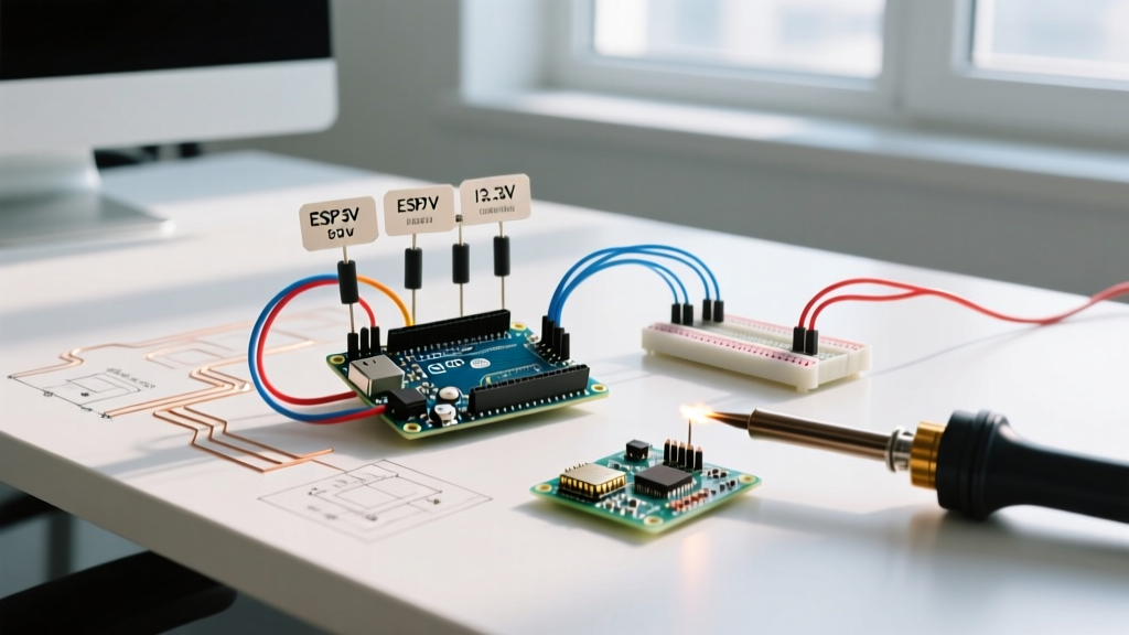
ESP32 Migration Warning: If you are migrating your buzzer and Arduino code from an Uno to an ESP32, the nativetone()function behaves differently. The ESP32 does not use the same AVR timer architecture. Instead, community best practice in 2026 dictates using theledcWriteTone()function via the LEDC (LED Control) peripheral. This offloads the square wave generation to dedicated hardware, freeing the dual-core CPU for Wi-Fi and Bluetooth stack management without audio stuttering.
Acoustic Impedance and Enclosure Resonance
A frequent complaint on maker subreddits is that a passive piezo buzzer sounds 'thin' or 'quiet' when tested on a breadboard. Piezo elements require an acoustic cavity to amplify specific frequencies. The community workaround is to mount the piezo disc against a hollow plastic enclosure using double-sided foam tape, ensuring the center of the disc remains free to vibrate. Alternatively, purchasing a pre-enclosed passive buzzer with a built-in resonance chamber (like the CMT-1603) yields a 10dB to 15dB increase in perceived loudness compared to a bare disc.
Where to Source Community Schematics in 2026
For those looking to dive deeper into specific implementations, the following community hubs remain the gold standard for verified schematics and code repositories:
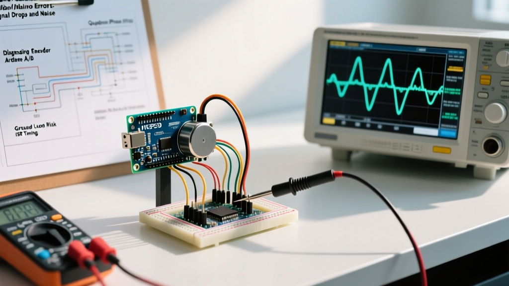
- Hackaday.io: Search for 'piezo haptic feedback' or 'RTTTL alarm'. Hackaday project logs often include detailed oscilloscope captures of buzzer waveforms, helping you visualize the exact duty cycle distortions caused by improper transistor biasing.
- GitHub Topics: Browsing the
arduino-buzzerandrtttltags yields dozens of optimized, memory-efficient melody players tailored for ATtiny85 and ESP8266 environments where SRAM is severely limited. - Electronics StackExchange: The premier destination for debugging hardware-level failures, such as diagnosing why a MOSFET-driven buzzer circuit is experiencing thermal runaway or high-frequency ringing.
By leveraging these community resources, respecting the electrical limits of your GPIO pins, and choosing the correct library for your specific microcontroller architecture, you can elevate your buzzer and Arduino projects from noisy prototypes to polished, reliable consumer-grade devices.