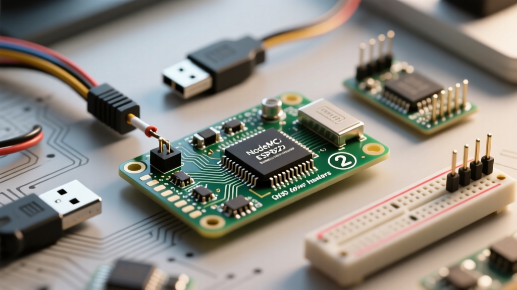

The NodeMCU ESP8266 remains a cornerstone of IoT prototyping and general maker electronics. Despite its maturity, developers frequently encounter cryptic compilation errors, upload failures, and runtime crashes that can halt a project for hours. Unlike standard Arduino AVR boards, the ESP8266 operates on a complex RTOS (Real-Time Operating System) background layer, manages its own Wi-Fi stack, and relies on specific hardware strapping pins during boot. Understanding the silicon-level quirks of this microcontroller is essential for effective troubleshooting.
The Anatomy of a NodeMCU ESP8266 Upload Failure
The most infamous error in the ESP8266 ecosystem is the upload timeout. When the Arduino IDE attempts to flash a new sketch, it communicates with the onboard bootloader via UART. If this handshake fails, the IDE throws a fatal error, leaving the board unresponsive.
Scenario 1: "Timed Out Waiting for Packet Header"
This error occurs when the esptool cannot force the ESP8266 into UART bootloader mode. The ESP8266 determines its boot mode by sampling specific "strapping pins" during the first few milliseconds of power-on. If these pins are not in the correct state, the chip will attempt to boot from its existing flash memory or SDIO, completely ignoring the USB serial connection.
- GPIO0: Must be pulled LOW (connected to GND) during boot to enter flash mode. On a NodeMCU, the onboard "FLASH" button grounds this pin. If your code or external circuitry is pulling GPIO0 HIGH, the upload will fail.
- GPIO2: Must be HIGH or floating. If pulled LOW, the chip enters an undocumented serial bootloader that is incompatible with standard Arduino uploads.
- GPIO15: Must be LOW. If GPIO15 is pulled HIGH, the ESP8266 attempts to boot from an external SDIO slave, bypassing the SPI flash and UART entirely.
The Fix: Disconnect all external wiring from GPIO0, GPIO2, and GPIO15. Hold the onboard "BOOT" or "FLASH" button, press the "RST" button, release the RST button, and then release the FLASH button. This manually forces the strapping pins into the correct UART download state before initiating the upload in the Arduino IDE.
Scenario 2: The CH340 vs. CP2102 Driver Conflict
NodeMCU boards utilize a USB-to-UART bridge chip to communicate with your PC. Early V2 (Amica) boards typically use the Silicon Labs CP2102, while the more common V3 (LoLin) boards use the WCH CH340G. Windows 10 and 11 often auto-install a generic, outdated CH340 driver (version 3.4.x) which silently drops packets at baud rates above 115200.
The Fix: Open your Device Manager, locate the USB-SERIAL CH340 device, and manually update the driver to version 3.5.2019 or newer. Additionally, in the Arduino IDE Tools menu, force the Upload Speed down to 115200. While the ESP8266 can theoretically flash at 921600 baud, cheap USB cables with high capacitance will cause signal degradation at high speeds, resulting in timeout errors.
Decoding Runtime Exceptions: When the Sketch Compiles but Crashes
Successfully uploading your code is only half the battle. Because the NodeMCU ESP8266 runs a background Wi-Fi stack, your loop() function is essentially sharing CPU time with the RF subsystem. If your code hogs the processor, the hardware Watchdog Timer (WDT) will forcefully reset the chip to prevent network lockups.
Exception (28) and the Watchdog Timer (WDT) Reset
If your serial monitor outputs Exception (28): epc1=0x4020102a followed by a stack trace and a reboot, you have triggered a LoadProhibitedCause or a software watchdog reset. This almost always happens when a while() loop or a long-running for() loop blocks the main thread for more than 3.2 seconds without yielding to the RTOS.
// BAD: Blocks the Wi-Fi stack, triggers WDT reset
while (digitalRead(SENSOR_PIN) == LOW) {
  // waiting for sensor
}

// GOOD: Yields CPU cycles to the background RTOS
while (digitalRead(SENSOR_PIN) == LOW) {
  yield(); // or delay(1);
}
Using yield() or delay(1) feeds the software watchdog and allows the ESP8266 to process background Wi-Fi keep-alive packets. For hardware-intensive tasks, consider utilizing the ESP8266 Arduino Core asynchronous libraries, such as ESPAsyncWebServer, which eliminate blocking loops entirely.
Exception (9): LoadStoreAlignmentCause
Exception 9 occurs when your code attempts to read or write a 32-bit integer to a memory address that is not divisible by 4. The Xtensa LX106 architecture inside the ESP8266 strictly enforces memory alignment. This frequently happens when casting raw byte arrays (from Wi-Fi payloads or I2C sensors) directly into 32-bit integers or floats using pointer casting.
The Fix: Never cast a uint8_t* directly to a uint32_t*. Instead, use the memcpy() function to safely transfer the bytes into a properly aligned 32-bit variable.
Flash Memory & Board Manager Mismatches
The NodeMCU ESP8266 typically ships with a 4MB (32Mbit) SPI flash chip. However, the Arduino IDE defaults to treating it as a 1MB chip unless configured correctly. If your sketch includes a filesystem (SPIFFS or LittleFS) for storing HTML files or OTA firmware binaries, a mismatch between the physical flash and the IDE partition map will result in silent data corruption or boot loops.
| IDE Flash Size Setting | Sketch Space | Filesystem (SPIFFS/LittleFS) | Use Case Scenario |
|---|---|---|---|
| 4MB (FS:1MB OTA:~1019KB) | 1019 KB | 1 MB | Standard IoT sensors with basic web UI |
| 4MB (FS:2MB OTA:~1019KB) | 1019 KB | 2 MB | Data logging, moderate local storage |
| 4MB (FS:3MB OTA:~512KB) | 512 KB | 3 MB | Heavy web servers, audio files, no OTA |
| 1MB (FS:64KB OTA:~470KB) | 470 KB | 64 KB | Legacy ESP-01 modules, minimal code |
Always verify your physical flash size using the ESP.getFlashChipRealSize() function in your setup routine. If the IDE is set to 4MB but the chip is actually 1MB (common on counterfeit clones), the ESP8266 will crash when attempting to write to memory addresses beyond the physical silicon limits.
Advanced Diagnostic Tools for the ESP8266
When the serial monitor spits out a wall of hexadecimal memory addresses, guessing the source of the crash is futile. To bridge the gap between raw memory dumps and your C++ source code, you must use the EspExceptionDecoder plugin for the Arduino IDE. By pasting the stack trace from the serial monitor into the decoder, it maps the hexadecimal addresses directly to the exact line numbers in your sketch where the fault occurred.
Monitoring Heap Fragmentation
Memory leaks on the ESP8266 rarely manifest as immediate crashes. Instead, they cause "heap fragmentation." As your sketch dynamically allocates and frees memory (e.g., parsing JSON strings from an API), the free RAM becomes divided into tiny, unusable chunks. Eventually, a request for a contiguous block of memory fails, triggering an Exception 29 (StoreProhibitedCause).
Implement a heap diagnostic print in your main loop to track memory health over time:
void loop() {
  static unsigned long lastCheck = 0;
  if (millis() - lastCheck > 5000) {
    lastCheck = millis();
    Serial.printf("Free Heap: %u bytes | Max Block: %u bytes\n",
                  ESP.getFreeHeap(), ESP.getMaxFreeBlockSize());
  }
  // Your application logic here
}
If ESP.getFreeHeap() slowly decreases over hours of operation, you have a memory leak. If the total free heap remains high, but ESP.getMaxFreeBlockSize() drops near zero, you are suffering from severe fragmentation. Transitioning from the standard String class to fixed-size char arrays or utilizing the String::reserve() method will drastically improve long-term stability.
Pro-Tip from the Workbench: Never rely on the NodeMCU's onboard 3.3V voltage regulator to power external sensors or relays. The onboard AMS1117-3.3 regulator is typically rated for a maximum of 800mA, but it lacks adequate heatsinking on the PCB. Drawing more than 300mA continuously will cause thermal throttling, resulting in brownouts that manifest as random Wi-Fi disconnects and spontaneous reboots. Always use an external buck converter for peripheral power, tying the grounds together as detailed in the NodeMCU Official Documentation.
Mastering NodeMCU ESP8266 error diagnosis requires shifting your mindset from simple microcontroller programming to embedded systems management. By respecting the hardware strapping pins, utilizing proper USB-UART drivers, yielding to the RTOS, and actively monitoring heap allocation, you can transform an unreliable prototype into a robust, production-ready IoT device.