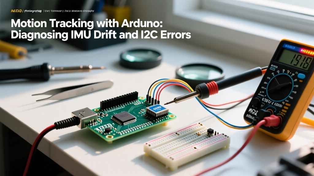

Mastering Motion Tracking with Arduino: A Diagnostic Guide
Building a reliable motion tracking system with Arduino is a rite of passage for robotics and IoT engineers. Whether you are balancing a self-navigating rover, stabilizing a camera gimbal, or capturing biomechanical data, Inertial Measurement Units (IMUs) are the core of your spatial awareness. However, the journey from raw sensor data to accurate orientation is fraught with hardware bottlenecks and mathematical pitfalls. As of 2026, while sensor hardware has become incredibly cheap, the physics of motion tracking remain unforgiving.
This comprehensive diagnostic guide targets the most persistent errors encountered during motion tracking with Arduino projects. We will bypass basic wiring tutorials and dive straight into the weeds of I2C bus lockups, Z-axis gyroscopic drift, high-frequency vibration aliasing, and magnetic calibration failures. By understanding the root causes of these errors, you can transition from a frustrating trial-and-error workflow to a deterministic, engineering-grade approach.
The I2C Bus Lockup: Why Your Arduino Freezes Mid-Flight
The most catastrophic error in Arduino motion tracking is the silent I2C bus lockup. Your code is running perfectly, and suddenly, the microcontroller freezes. The serial monitor stops printing, and your servos lock in place. This is almost always caused by a failure in the Wire library during an I2C transaction.
Root Cause Analysis: Capacitance and Pull-Up Weakness
The I2C protocol is an open-drain bus that relies on external pull-up resistors to bring the SDA and SCL lines back to a HIGH state. The ATmega328P (used in the Arduino Uno and Nano) has internal pull-up resistors, but they are typically between 30kΩ and 50kΩ. These are far too weak for high-speed I2C communication or buses with high capacitance.
- The 400pF Limit: The I2C specification limits total bus capacitance to 400pF. Long jumper wires, breadboard contacts, and multiple sensors quickly add up. Standard ribbon cable adds roughly 1.5pF to 2pF per centimeter.
- Rise Time Failure: If the pull-up resistor is too large (weak) and the capacitance is too high, the RC time constant increases. The voltage on the SCL line fails to reach the logic HIGH threshold before the next clock cycle begins, causing the Arduino Wire Library to hang indefinitely while waiting for an acknowledgment (ACK) bit.
The Diagnostic Fix
To resolve I2C lockups in motion tracking setups, you must aggressively manage bus impedance. First, disable internal pull-ups in your code if your breakout board lacks them, and solder external resistors directly to the SDA and SCL lines near the IMU. For standard 100kHz I2C, use 4.7kΩ resistors. If you are pushing the bus to 400kHz (Fast Mode) to increase your sensor sampling rate, drop the pull-ups to 2.2kΩ or even 1.5kΩ to ensure sharp rise times. Furthermore, keep I2C traces under 30cm and use twisted-pair wiring to minimize inductive crosstalk from nearby PWM motor signals.
Conquering Yaw Drift: The Gyro Integration Trap
If your Arduino motion tracking system holds pitch and roll perfectly but slowly rotates on the Z-axis (yaw) over time, you are experiencing gyroscopic drift. This is not a defect; it is a fundamental limitation of integrating angular velocity over time.
Why Yaw Drifts and Pitch/Roll Do Not
Pitch and roll can be continuously corrected using the accelerometer, which measures the constant vector of Earth's gravity. The Z-axis (yaw), however, rotates parallel to the gravity vector. The accelerometer cannot detect this rotation. Therefore, yaw relies entirely on integrating the gyroscope's Z-axis output or referencing a magnetometer. Because MEMS gyroscopes have inherent bias instability (noise), integrating this noise over time results in a cumulative error, manifesting as yaw creep—often drifting 2 to 10 degrees per minute on budget sensors.
Solutions: Sensor Fusion and Hardware Upgrades
To fix yaw drift, you must implement sensor fusion. If you are using raw data from an older TDK InvenSense MPU6050, you must run a Madgwick or Mahony filter on the Arduino. These algorithms use the magnetometer to correct Z-axis drift while relying on the accelerometer for pitch/roll. However, running complex floating-point quaternion math on a 16MHz ATmega328P can bottleneck your loop rate.
The modern 2026 standard for professional motion tracking with Arduino is to offload this math to a dedicated sensor hub. The Bosch BNO085 and BNO086 IMUs feature an internal ARM Cortex-M0+ that runs proprietary SH-2 sensor fusion algorithms at 500Hz. By upgrading to a BNO086 breakout (typically $28-$35), your Arduino simply reads the pre-calculated, drift-free quaternion data via SPI or I2C, entirely eliminating integration drift and freeing up your MCU for high-level logic.
IMU Selection Matrix for 2026 Projects
Choosing the wrong sensor is a fundamental architectural error. Use this matrix to match your IMU to your project's tolerance for drift and processing overhead.
| IMU Model | Approx. Price (2026) | On-Chip Fusion | Yaw Drift Profile | Best Use Case |
|---|---|---|---|---|
| MPU6050 (Clone) | $2 - $4 | No (DMP is deprecated/complex) | High (Requires MCU Madgwick filter) | Basic toys, low-budget learning |
| BMI270 | $10 - $14 | No (Requires external MCU fusion) | Medium (Excellent low-noise gyro) | Drones, high-vibration robotics |
| BNO085 / BNO086 | $28 - $35 | Yes (SH-2 Sensor Hub) | Negligible (Magnetometer corrected) | VR tracking, gimbals, rovers |
| ICM-42688-P | $15 - $20 | No (High-performance raw data) | Low (Industrial grade bias stability) | High-speed flight controllers |
Vibration Aliasing and the Nyquist Limit
When mounting an IMU on a chassis with DC motors, stepper motors, or propellers, you may notice erratic, massive spikes in your acceleration and orientation data. This is rarely a software bug; it is mechanical resonance causing high-frequency aliasing.
The Diagnosis: Sampling Rate vs. Vibration Frequency
If your Arduino polls the IMU at 100Hz, the Nyquist-Shannon sampling theorem dictates that you can only accurately measure frequencies up to 50Hz. If your chassis vibrates at 150Hz due to a motor, that high-frequency noise will 'fold back' into your sampling bandwidth, appearing as chaotic, low-frequency noise that destroys your sensor fusion algorithm's stability.
The Fix: Digital Low-Pass Filtering (DLPF)
Before the data ever reaches the Arduino, the IMU's internal hardware filter must truncate the noise. If you are configuring an MPU6050 or BMI270, you must write to the sensor's configuration register to enable the Digital Low-Pass Filter (DLPF). For example, writing 0x03 to the MPU6050's CONFIG register (Address 0x1A) sets the accelerometer bandwidth to 42Hz and the gyroscope bandwidth to 42Hz. This aggressively smooths out high-frequency motor harmonics. Additionally, physically isolate the IMU breakout board using Sorbothane dampening pads or a 3D-printed TPU mount to decouple structural resonance from the silicon die.
Pro-Tip on Logic Level Shifting: Many modern, high-performance IMUs (like the BMI270 and BNO086) operate strictly at 3.3V logic and are not 5V tolerant. Connecting them directly to an Arduino Uno's 5V I2C pins will degrade the sensor's internal voltage regulators over time, leading to thermal drift and eventual silicon failure. Always use a dedicated bi-directional logic level shifter (like the BSS138 MOSFET-based shifters) when interfacing 3.3V IMUs with 5V Arduinos.
Magnetic Calibration and Hard Iron Distortion
If you are using a 9-DOF IMU (which includes a magnetometer to fix yaw drift), you will encounter hard and soft iron distortion errors. Hard iron distortion is caused by permanent magnetic fields (like nearby neodymium motors or speakers) adding a constant offset to the magnetometer readings. Soft iron distortion is caused by ferromagnetic materials (like steel chassis plates) bending the Earth's magnetic field lines.
Calibration Protocol
To diagnose and fix this, you must perform a dynamic calibration routine. Write a sketch that records the raw X, Y, and Z magnetometer values while you physically rotate the Arduino in a full 3D sphere (the 'figure-8' motion). Plot these points; instead of a perfect sphere centered at (0,0,0), you will see an offset ellipsoid. Calculate the offset center and apply these subtraction values in your code before feeding the data into your fusion filter. Crucially, mount your IMU at least 10cm away from high-current-carrying wires and stepper motors, as the electromagnetic field generated by a 2A current draw will instantly saturate the magnetometer's sensing elements.
Frequently Asked Questions (FAQ)
Why does my IMU output jump to zero when I start my motors?
This is almost certainly an I2C bus voltage sag or electromagnetic interference (EMI) issue. When motors draw high stall current, the shared power rail voltage dips, causing the IMU to brownout and reset. Furthermore, unshielded motor wires emit massive EMI that corrupts I2C data packets. Use separate power regulators for your logic and your motors, and enable the IMU's internal CRC (Cyclic Redundancy Check) if supported by the chip.
Can I use an Arduino Uno for high-speed motion tracking?
While possible, the Uno's 16MHz ATmega328P lacks a hardware Floating Point Unit (FPU). Running complex quaternion math (like the Madgwick filter) requires software-based floating-point emulation, which severely limits your loop rate to roughly 50-100Hz. For high-speed tracking (200Hz+), upgrade to an Arduino Nano 33 BLE Sense (Cortex-M4F with FPU) or a Teensy 4.1.
My BNO085 is outputting 'Sensor Hub Error' on startup. How do I fix it?
The BNO085 requires a specific initialization sequence and a stable 3.3V supply capable of delivering at least 150mA during its boot sequence. If your Arduino's 3.3V regulator is underpowered, the sensor hub will fail to load its internal firmware patch. Power the breakout board via an external 3.3V LDO regulator rather than relying on the Arduino's onboard 3.3V pin.