
When transitioning an Arduino project from a breadboard prototype to a standalone deployment, relying on a PC USB connection is no longer viable. Understanding how to properly implement an Arduino external power supply is critical to prevent brownouts, thermal throttling, and permanent board damage. Whether you are building an automated greenhouse controller or a motorized robotics chassis, selecting the right power delivery method dictates the reliability of your microcontroller.
This comprehensive quick-reference guide and FAQ addresses the most common pitfalls makers face when moving beyond USB power, updated with component insights and market realities for 2026.
Quick Reference Matrix: Board Power Limits
Not all boards handle external voltage identically. The onboard linear regulator is the primary bottleneck. Below is a quick-reference matrix for the most common development boards.
| Board Model | Recommended Input (Barrel/Vin) | Onboard Regulator IC | Safe Max Current @ 12V In | Reverse Polarity Protection? |
|---|---|---|---|---|
| Arduino Uno R3 | 7V - 12V | NCP1117ST50T3G (1A) | ~200mA | Yes (P-Channel MOSFET) |
| Arduino Mega 2560 | 7V - 12V | NCP1117ST50T3G (1A) | ~200mA | Yes (P-Channel MOSFET) |
| Arduino Nano (Classic) | 7V - 12V | LM1117-5.0 or AMS1117 | ~100mA | No (Often omitted on clones) |
| Generic ESP32 DevKit V1 | 5V (Micro-USB/5V Pin only) | AMS1117-3.3 (800mA) | ~300mA (at 5V In) | No |
The Barrel Jack vs. Vin Pin: Which Should You Use?
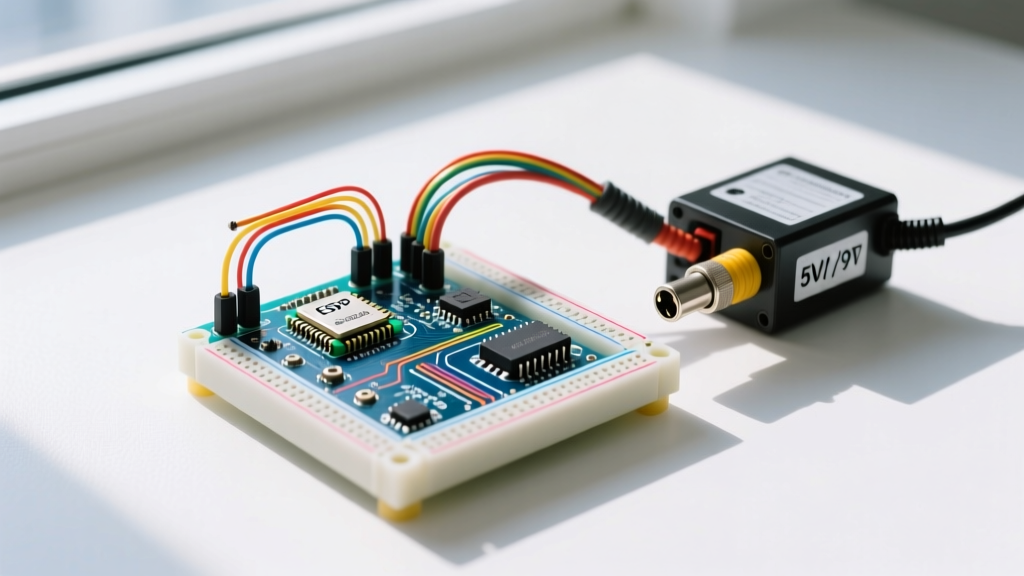
A frequent question in the maker community is whether to plug a battery pack or wall adapter into the DC barrel jack or wire it directly to the Vin pin. Electrically, on most standard Arduino boards, these two paths are directly connected. However, there is a crucial hardware difference regarding safety.
On the official Arduino Uno Rev3, the barrel jack circuit includes a P-channel MOSFET (typically an FDN340P) that acts as a reverse polarity protection diode. If you accidentally swap the positive and negative wires on your power supply, the MOSFET remains off, protecting the board. If you wire that same reversed supply directly to the Vin pin, you bypass the MOSFET and will instantly destroy the onboard voltage regulator and potentially the ATmega328P microcontroller.
Best Practice: Always use the barrel jack when available. If your board lacks a barrel jack (like the Nano) or you are designing a custom PCB shield, ensure you add a Schottky diode or a P-FET reverse polarity protection circuit before the Vin net.
Thermal Limits: Why Your Arduino Shuts Down at 12V
The most common failure mode when using an Arduino external power supply is thermal throttling of the onboard linear regulator. Linear regulators operate by burning off excess voltage as heat. We can calculate this heat dissipation using the formula:
Power Dissipated (Pd) = (Input Voltage - Output Voltage) × Current Draw
Let us look at a real-world scenario. You power an Arduino Uno with a 12V wall adapter. The onboard NCP1117 regulator steps this down to 5V. You connect a few sensors and an LCD screen, drawing 200mA (0.2A) from the 5V rail.
- Pd = (12V - 5V) × 0.2A = 1.4 Watts.
- According to the ON Semiconductor NCP1117 datasheet, the SOT-223 package has a junction-to-ambient thermal resistance of roughly 50°C/W.
- Temperature Rise = 1.4W × 50°C/W = 70°C.
- Adding a 25°C room temperature ambient, the regulator junction sits at 95°C.
While 95°C is hot to the touch, it is below the 125°C thermal shutdown threshold. However, if you add a servo motor or a high-power Wi-Fi module drawing 350mA, the dissipation jumps to 2.45W. The junction temperature will exceed 145°C, triggering the internal thermal protection circuit. The Arduino will randomly reset or shut down completely. This is why stepping down 12V to 5V using a linear regulator is highly inefficient for high-current projects.
Expert Warning: Never route high-draw peripherals (like servos, stepper motors, or long LED strips) through the Arduino's onboard 5V pin. Use a dedicated external switching buck converter (like an MP2315 or LM2596 module) to generate 5V directly from your main power supply, and simply tie the grounds together.
Sizing Your External Wall Adapter in 2026
When purchasing a dedicated AC/DC wall adapter for a permanent installation, you must size the current capacity correctly. A general engineering rule of thumb is to select a power supply rated for at least 30% more current than your project's maximum calculated draw. This keeps the adapter operating in its peak efficiency curve and prevents overheating.
For a standard IoT sensor node drawing 150mA at 12V, a 500mA adapter is sufficient. However, be wary of ultra-cheap, unbranded adapters found on bulk e-commerce sites. In 2026, high-quality, medically-rated or ITE-certified adapters from brands like Mean Well (e.g., the GST220A12 series, typically priced around $18 to $24) offer genuine overcurrent protection, low ripple noise (<50mV), and proper isolation. Unbranded $4 adapters often output 11.2V under load and can introduce high-frequency switching noise that disrupts the Arduino's analog-to-digital converter (ADC) readings.
Frequently Asked Questions (FAQ)
Can I power an Arduino externally using a standard 9V alkaline battery?
While technically possible, it is highly discouraged for anything beyond a brief demonstration. A standard 9V alkaline battery has a very low energy capacity (typically 400mAh to 550mAh) and a high internal resistance. As the Arduino draws current, the battery's voltage will rapidly sag. Because the NCP1117 regulator requires a 'dropout voltage' of about 1.2V above the 5V output, the battery voltage must stay above 6.2V. In reality, a 9V battery will drop below this threshold within a few hours, causing the Arduino to brownout and reset continuously. For portable projects, use a 2S (7.4V) or 3S (11.1V) LiPo battery pack with a low-dropout regulator or a buck converter.
What happens if I feed 5V directly into the '5V' pin?
Injecting a regulated 5V directly into the 5V pin bypasses the onboard linear regulator entirely. This is highly efficient because no power is wasted as heat. However, you also bypass all onboard protection circuitry. There is no reverse polarity protection, no overvoltage protection, and no filtering. If your external 5V supply has a voltage spike (e.g., jumping to 6V due to a faulty switching regulator), it will feed directly into the ATmega328P's VCC line, likely destroying the microcontroller. Only use the 5V pin if you are using a highly reliable, clean power source and are confident in your wiring.
Is it safe to have the USB cable plugged in while the external power supply is connected?
On genuine Arduino boards (like the Uno R3 and Mega 2560), yes. These boards feature a comparator circuit (usually an LMV331) that monitors the external Vin. If the voltage at the barrel jack exceeds roughly 6.6V, the comparator triggers a P-channel MOSFET to disconnect the USB VBUS line. This prevents the external power from backfeeding into your computer's USB port, which could damage your motherboard. However, many cheap clone boards omit this comparator to save costs. On clone boards, plugging in both USB and a 12V barrel jack can result in 12V being pushed back into your PC's 5V USB line, causing catastrophic damage to your computer.
How do I eliminate noise on the ADC when using a switching power supply?
Switching power supplies (buck converters and wall adapters) generate high-frequency ripple that can cause erratic readings on the Arduino's analog pins. To mitigate this, place a 100nF (0.1µF) ceramic capacitor as close to the AREF and GND pins as possible. Additionally, use the analogReference(EXTERNAL) function in your sketch and feed a clean, dedicated 3.3V or 4.096V reference voltage into the AREF pin, rather than relying on the noisy 5V rail as your baseline.
Final Troubleshooting Checklist
If your externally powered Arduino is failing to boot or resetting randomly, run through this diagnostic sequence:
- Measure under load: Use a multimeter to check the voltage at the barrel jack while the circuit is active. Ensure it does not drop below 7V.
- Check the regulator temperature: Carefully touch the metal tab of the voltage regulator. If it is too hot to keep your finger on for more than two seconds, you are exceeding its thermal limits. Lower the input voltage to 7.5V or use an external buck converter.
- Inspect for ground loops: If communicating via RS485 or long I2C lines to external modules, ensure all grounds are properly tied together at a single star-ground point to prevent logic-level shifting errors.