
The Ultimate Stepper Controller Arduino Quick-Reference
Integrating a stepper controller Arduino setup is a foundational skill for CNC routing, 3D printing, and precision robotics. However, the transition from basic LED blinking to managing inductive motor loads introduces complex hardware and software challenges. Whether you are dealing with missed steps, thermal shutdowns, or mid-band resonance, selecting and configuring the right driver IC is critical.
This FAQ and quick-reference guide cuts through the fluff, providing exact voltage formulas, wiring topologies, and library recommendations for the three most dominant stepper drivers in the maker ecosystem as of 2026: the A4988, DRV8825, and TMC2209.
2026 Driver Comparison Matrix
Before diving into troubleshooting, it is essential to match the driver IC to your mechanical load and acoustic requirements. Below is a technical comparison of the most common carrier boards available on the market.
| Driver IC | Max Continuous Current | Microstepping | Interface | Typical 2026 Price | Best Use Case |
|---|---|---|---|---|---|
| A4988 | 1.0A (1.5A w/ cooling) | Up to 1/16 | STEP/DIR | $2.00 - $3.50 | Basic prototyping, low-cost plotters |
| DRV8825 | 1.5A (2.2A w/ cooling) | Up to 1/32 | STEP/DIR | $4.00 - $6.00 | Standard 3D printers, light CNC mills |
| TMC2209 | 1.2A (2.0A w/ cooling) | Up to 1/256 | STEP/DIR + UART | $8.00 - $12.00 | Silent operation, sensorless homing, advanced robotics |
Hardware Wiring & Configuration FAQ
Q: How do I accurately set the Vref current limit?
Setting the reference voltage (Vref) incorrectly is the number one cause of dead stepper drivers and stalled motors. You must use a digital multimeter to measure the voltage between the GND pin and the Vref test point (usually the wiper on the top trim potentiometer) while the board is powered via the logic pin (VDD), not the motor power supply (VMOT).
- DRV8825 Formula:
Vref = Current Limit / 2. For a standard 1.5A NEMA 17 motor, set Vref to 0.75V. (Assumes a 0.100Ω sense resistor, standard on Pololu DRV8825 carriers). - A4988 Formula:
Vref = Current Limit × 8 × Rs. With a standard 0.100Ω sense resistor, the formula simplifies toVref = Current Limit × 0.8. For a 1.0A limit, set Vref to 0.8V. - TMC2209 (UART Mode): You do not need to set Vref manually via the potentiometer. Instead, set the RMS current limit dynamically in your Arduino code using the
driver.rms_current(1200)command (value in milliamps).
Q: Why is a 100µF capacitor mandatory on VMOT?
Stepper motors are highly inductive loads. When the driver's internal MOSFETs switch off, the collapsing magnetic field generates massive voltage spikes (back-EMF) that can easily exceed the 35V-45V absolute maximum rating of the driver IC, destroying it instantly. You must solder a 100µF to 220µF electrolytic capacitor (rated for at least 1.5x your supply voltage, e.g., 35V or 50V for a 24V system) directly across the VMOT and GND pins on the carrier board. Place it as close to the board as physically possible to minimize trace inductance.
Q: Should I use a 12V or 24V power supply for NEMA 17 motors?
Always use 24V if your driver supports it. Stepper motor torque drops significantly at higher RPMs due to coil inductance resisting rapid current changes. A 24V supply forces current into the coils twice as fast as a 12V supply, effectively doubling your usable torque envelope above 300 RPM. The driver's internal switching regulator handles the voltage drop, dissipating the excess energy as heat—which is why adequate heatsinking and active airflow are required at 24V.
Code, Libraries & UART FAQ
Q: AccelStepper vs. MobaTools: Which is better for modern MCUs?
For years, the AccelStepper Library was the undisputed standard for Arduino stepper control. However, AccelStepper relies on software polling via the run() or runSpeed() functions, which must be called thousands of times per second in your main loop. If your code includes blocking functions (like delay(), SD card writes, or heavy I2C sensor reads), the motor will stutter or stall.
The 2026 Recommendation: Use MobaTools. MobaTools utilizes hardware timer interrupts to generate step pulses in the background. This guarantees perfectly timed microstepping and acceleration profiles even if your main loop() is blocked by WiFi stack operations on an ESP32 or complex serial parsing on an Arduino Mega.
Q: How do I wire a TMC2209 for UART without backfeeding?
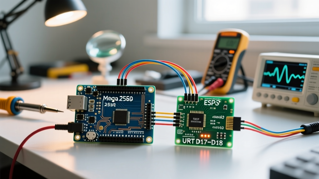
The TMC2209 Stepper Motor Driver allows you to configure microstepping, enable StealthChop2, and read stallGuard values via a single-wire UART connection. However, connecting an Arduino TX pin directly to the TMC RX pin can cause backfeeding issues, where the driver powers the Arduino through the serial line when VMOT is on but VDD is off.
Correct UART Wiring Topology:
- Connect Arduino RX directly to TMC2209 TX.
- Place a 1kΩ resistor in series between the Arduino TX and the TMC2209 RX.
- Use the
TMCStepperlibrary by teemuatlut. Initialize withTMC2209Stepper driver(&Serial1, R_SENSE, DRIVER_ADDRESS);.
Advanced Troubleshooting & Edge Cases
Q: My motor stalls or makes a loud grinding noise at mid-range speeds (150–250 RPM).
This is a classic symptom of mid-band resonance, a physical phenomenon inherent to 1.8° hybrid stepper motors where the rotor overshoots the magnetic field, causing a loss of synchronization and torque.
Pro-Tip: If you are using a DRV8825, switch the decay mode. The DRV8825 defaults to a mixed-decay mode that can exacerbate resonance. If you are using a TMC2209, switch from StealthChop2 (silent, voltage-based) to SpreadCycle (current-based, higher torque) via UART when crossing the 150 RPM threshold, or simply increase the acceleration rate to pass through the resonant frequency band as quickly as possible.
Q: The driver enters thermal shutdown after 10 minutes of operation.
Both the A4988 and DRV8825 have internal thermal shutdown thresholds (typically around 150°C to 165°C die temperature). If your driver shuts down mid-print or mid-cut:
- Verify Airflow: Passive aluminum heatsinks are largely ineffective without directed airflow. A 5V 40mm fan blowing directly across the finned heatsink drops thermal resistance by up to 60%.
- Check the Sense Resistor: Cheap clone boards often use 0.15Ω sense resistors instead of 0.10Ω. If your Vref calculation assumes 0.10Ω, you are actually pushing 50% more current than intended, leading to rapid overheating. Measure the sense resistor with a multimeter; if it reads 150mΩ, recalculate your Vref accordingly.
- Reduce Holding Current: Use the
driver.HoldMultiplier(0.5)command in TMCStepper, or implement a software pin-toggle to drop the current limit when the motor is stationary. Motors rarely need 100% torque to hold a static position.
Q: What gauge wire should I use between the driver and the NEMA 17 motor?
For runs under 1 meter, use 22 AWG stranded copper wire. Thicker wire (like 18 AWG) increases the parasitic capacitance between the motor leads, which can interact with the high-frequency PWM switching of the TMC2209 (up to 45kHz), causing the driver to falsely detect short circuits and shut down. Keep the four motor wires bundled together to minimize EMI radiation, but avoid routing them parallel to sensitive endstop or UART signal wires.