
The Dual Meaning: Trademark Silkscreens vs. Boot Screens
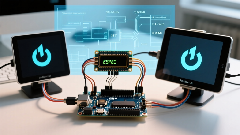
When makers and engineers search for logo Arduino configurations, they are typically navigating one of two distinct challenges: applying the official trademarked logo to a custom PCB silkscreen, or programming a custom pixel-art boot logo onto an Arduino-driven display. This guide focuses heavily on the latter—configuring and optimizing boot sequences for SSD1306 OLED and ILI9341 TFT displays—while briefly addressing the legal and technical parameters of the official trademark.
Trademark Note: If you are designing a custom shield and intend to print the official logo Arduino on the silkscreen, you must adhere strictly to the Arduino Trademark Guidelines. The infinity symbol must not be distorted, and the wordmark must use the exact official typography. For open-source hardware derivatives, the community logo (the gear with a plus/minus sign) is the legally safe alternative.
Hardware Configuration and Pinout Matrices
Displaying a high-fidelity boot logo requires precise hardware configuration. The interface protocol (I2C vs. SPI) dictates your wiring, clock speeds, and ultimately, your boot time.
SSD1306 OLED (128x64, I2C Interface)
The 0.96-inch SSD1306 OLED is the standard for monochrome boot logos. It operates on I2C, which is slower than SPI but requires only two data pins.
- VCC: 3.3V or 5V (check your breakout board regulator).
- GND: Common ground.
- SCL: A5 (on ATmega328P) or GPIO 22 (on ESP32).
- SDA: A4 (on ATmega328P) or GPIO 21 (on ESP32).
Expert Tip: If your I2C bus hangs during the boot logo initialization, you likely have a bus capacitance issue. Add 4.7kΩ pull-up resistors to both SDA and SCL lines if your breakout board lacks them.
ILI9341 TFT (320x240, SPI Interface)
For full-color boot logos, the ILI9341 TFT is the industry workhorse. It requires Hardware SPI to achieve acceptable boot times (under 200ms for a full-screen draw).
- SCK: Pin 13 (Hardware SPI Clock)
- MOSI: Pin 11 (Hardware SPI Data)
- CS: Pin 10 (Chip Select, active LOW)
- DC: Pin 9 (Data/Command selector)
- RST: Pin 8 (Reset, active LOW)
Bitmap Conversion: Preparing Your Asset
You cannot pass a standard PNG or JPG directly to a microcontroller. The image must be converted into a C-style hex array. The Adafruit GFX Library Guide outlines the foundational graphics primitives, but for custom logos, you need a bitmap converter.
- Resize and Dither: Scale your image to the exact display resolution (128x64 or 320x240). Use Floyd-Steinberg dithering for monochrome OLEDs to preserve shading.
- Use img2cpp: Navigate to the open-source image2cpp web tool.
- SSD1306 Settings: Set color depth to 1-bit (black and white). Crucially, set the byte orientation to Vertical if using Adafruit libraries, or Horizontal if using the U8g2 Library Wiki standard.
- ILI9341 Settings: Set color depth to 16-bit (RGB565). Ensure the output format is set to a standard C byte array.
Memory Management: The SRAM Bottleneck
The most common failure mode when configuring a boot logo Arduino project is SRAM exhaustion. The ATmega328P (Arduino Uno/Nano) has only 2,048 bytes of SRAM.
Monochrome OLED Math
A 128x64 1-bit image requires exactly 1,024 bytes of memory (128 * 64 / 8). If you load this array into standard SRAM, you consume 50% of the Uno's available memory before your setup() function even finishes. This leads to stack collisions and random reboots.
The Solution: You must store the logo array in Flash memory using the PROGMEM keyword.
const unsigned char PROGMEM custom_logo [] = {
  0xff, 0xff, 0xff, 0xff, 0xc0, 0x03, 0x00, 0x00 // ... truncated hex data
};
Color TFT Math and the ESP32 Pivot
A 320x240 16-bit color image requires 153,600 bytes (153 KB). The ATmega328P has only 32 KB of total Flash memory. It is physically impossible to store a full-screen color boot logo on a standard Uno.
The Solution: You must either upgrade to a microcontroller with higher memory (like the ESP32, which has 520 KB of SRAM and up to 16 MB of Flash), or stream the logo from a MicroSD card using the SdFat library and draw it line-by-line using pushColors().
Display Controller Comparison Matrix
| Controller | Resolution | Color Depth | Interface | Memory Footprint | Recommended MCU |
|---|---|---|---|---|---|
| SSD1306 | 128x64 | 1-bit (Mono) | I2C / SPI | 1,024 Bytes | ATmega328P, ATTiny85 |
| SH1106 | 132x64 | 1-bit (Mono) | I2C / SPI | 1,056 Bytes | ATmega328P, ESP8266 |
| ST7789 | 240x240 | 16-bit (RGB565) | SPI | 115,200 Bytes | ESP32, Teensy 4.0 |
| ILI9341 | 320x240 | 16-bit (RGB565) | SPI | 153,600 Bytes | ESP32, SAMD21, RP2040 |
Code Implementation and SPI Clock Optimization
When drawing the logo from PROGMEM to a TFT display, the default SPI clock speed on many Arduino cores is conservative (often 4 MHz). This can result in a boot logo that takes over a second to draw, creating an undesirable flickering effect.
To achieve a snappy, professional boot sequence, manually configure the SPI clock divider in your initialization routine:
#include <SPI.h>
#include <Adafruit_ILI9341.h>

#define TFT_CS 10
#define TFT_DC 9
Adafruit_ILI9341 tft = Adafruit_ILI9341(TFT_CS, TFT_DC);

void setup() {
  // Overclock SPI to 24MHz (if supported by your wiring and breakout)
  SPI.beginTransaction(SPISettings(24000000, MSBFIRST, SPI_MODE0));
  tft.begin();
  tft.setRotation(3);

  // Draw the 16-bit color logo from PROGMEM
  tft.drawRGBBitmap(0, 0, (const uint16_t *)custom_logo_color, 320, 240);

  SPI.endTransaction();
}
Advanced Troubleshooting and Edge Cases
- The 'White Screen of Death' (TFT): If your TFT display powers on but remains stark white during the boot logo phase, your DC (Data/Command) pin is likely misconfigured or floating. The display is interpreting your pixel data as register commands. Verify the DC pin continuity with a multimeter.
- I2C Address Conflicts (OLED): The SSD1306 typically ships with an I2C address of
0x3C. However, some 132x64 SH1106 clones use0x3D. Run an I2C scanner sketch before hardcoding the address in your boot sequence. - PROGMEM Alignment Faults (ESP32): When porting 16-bit color arrays from an 8-bit AVR to a 32-bit ESP32, you may encounter cache alignment faults if the array is not word-aligned. Ensure your hex array is declared with the
__attribute__((aligned(4)))tag if using raw pointer casting.
Mastering the configuration of a custom boot sequence elevates a project from a breadboard prototype to a finished commercial product. Whether you are navigating the legalities of the official trademark or optimizing SPI bus timings for a 153KB color bitmap, precise memory management and hardware tuning are the keys to a flawless execution.