
Rethinking the Motor Controller Arduino Workflow
Integrating a motor controller with an Arduino is a rite of passage for robotics enthusiasts, yet it remains one of the most common sources of project failure. Most makers treat the motor driver as a simple plug-and-play peripheral, leading to spaghetti wiring, logic brownouts, and blocking code that ruins system responsiveness. In 2026, the standard for professional and advanced hobbyist robotics demands a systematic, optimized workflow. By standardizing your hardware selection, isolating power domains, and leveraging hardware-level timer interrupts, you can eliminate 90% of common debugging headaches before you even write your first line of C++.
This guide outlines a comprehensive workflow optimization strategy for pairing a motor controller with Arduino-based microcontrollers, focusing on the transition from legacy educational components to modern, high-efficiency MOSFET drivers.
Phase 1: Hardware Selection Matrix
The most critical optimization step occurs before you open your IDE. The ubiquitous L298N dual H-bridge has dominated educational kits for a decade, but its bipolar junction transistor (BJT) topology results in a massive voltage drop and severe thermal inefficiency. Modern workflows require Metal-Oxide-Semiconductor Field-Effect Transistor (MOSFET) based drivers.
| IC Model | Topology | Voltage Drop | Peak Current | 2026 Avg Price | Best Application |
|---|---|---|---|---|---|
| L298N | BJT H-Bridge | ~2.0V | 3.0A | $3.50 | Legacy / Basic Education |
| TB6612FNG | MOSFET | ~0.5V | 3.2A | $4.50 | Dual Small DC Motors (Rovers) |
| DRV8871 | MOSFET | ~0.4V | 3.6A | $6.00 | Single High-Torque Actuators |
| BTS7960 | MOSFET Half-Bridge | ~0.1V | 43A | $12.00 | Heavy Combat / Industrial Robotics |
For standard 12V rover platforms, the Pololu TB6612FNG Motor Driver Carrier is the undisputed workflow champion. Its low on-resistance (0.5 ohms) minimizes heat dissipation, allowing you to omit bulky heatsinks and shrink your overall enclosure footprint. For single, high-draw applications like linear actuators or winch motors, the Texas Instruments DRV8871 provides robust overcurrent protection and integrated decay mode selection, drastically reducing firmware complexity.
Phase 2: Power Domain Isolation and Wiring Standards
A motor is essentially a massive inductor. When you command a motor to stop or reverse, the collapsing magnetic field generates a flyback voltage spike that can easily exceed 50V. If your wiring workflow relies on shared breadboard rails, this noise will couple directly into your Arduino's 5V logic rail, causing spontaneous resets or corrupted I2C/SPI sensor data.
The Star Grounding Protocol
Never daisy-chain your grounds. Implement a 'star ground' topology where the battery negative terminal acts as the central hub. Run one heavy-gauge wire (14 AWG or thicker) from the battery to the motor controller power ground, and a separate, lighter wire (22 AWG) from the battery hub to the Arduino GND pin. This ensures that high-current motor return paths do not elevate the ground reference of your sensitive logic circuits.
Decoupling and Bulk Capacitance
Solder capacitors directly to the motor terminals or the controller's VIN/GND pins. The optimal 2026 standard for a 12V system drawing up to 5A is:
- Bulk Capacitor: 220µF to 470µF Low-ESR Electrolytic (rated for at least 25V) placed across the main power input to handle sudden current draws and prevent battery sag.
- High-Frequency Bypass: 0.1µF Ceramic capacitor placed as close to the motor controller IC's VCC and GND pins as possible to shunt high-frequency switching noise.
- Motor Terminals: 100nF ceramic capacitors soldered directly across the positive and negative terminals of the DC motors to suppress brush arcing EMI.
Expert Workflow Tip: If you are using a high-current module like the BTS7960, the logic enable pins (R_EN, L_EN) can sometimes backfeed voltage into the Arduino when the driver is unpowered. Always route logic signals through a cheap 4-channel optoisolator module (like the PC817-based boards) or use a dedicated logic-level MOSFET to physically isolate the 5V domains.
Phase 3: Firmware Optimization and Timer Management
The default Arduino analogWrite() function operates at approximately 490 Hz (or 980 Hz on pins 5 and 6). While functional, this low frequency falls squarely within the human hearing range, resulting in the annoying, high-pitched 'whine' characteristic of amateur robotics. Furthermore, relying on software loops to manage motor states blocks the MCU from processing sensor fusion or telemetry.
Shifting to Hardware Timer1 for 31kHz PWM
To optimize your workflow and eliminate audible noise, reconfigure the ATmega328P's Timer1 to operate in Phase and Frequency Correct PWM mode at 31.25 kHz. This pushes the switching frequency above human hearing and results in smoother current delivery to the motor windings.
// Optimized Timer1 Setup for 31kHz PWM on Pin 9 (OC1A)
void setupHighFreqPWM() {
  pinMode(9, OUTPUT);

  // Reset Timer1 control registers
  TCCR1A = 0;
  TCCR1B = 0;
  TCNT1  = 0;

  // Set top value for 31.25kHz at 16MHz clock
  // Formula: Top = (F_CPU / (2 * Prescaler * F_PWM)) - 1
  ICR1 = 255;

  // Configure Phase and Frequency Correct PWM
  TCCR1A |= (1 << COM1A1) | (1 << WGM11);
  TCCR1B |= (1 << WGM13) | (1 << WGM12) | (1 << CS10); // Prescaler = 1
}

// Function to set duty cycle (0 to 255)
void setMotorSpeed(uint16_t dutyCycle) {
  if (dutyCycle > 255) dutyCycle = 255;
  OCR1A = dutyCycle;
}
Non-Blocking State Machines
Abandon the delay() function entirely. Motor control requires constant monitoring of encoders, IMUs, and limit switches. Implement a lightweight state machine driven by millis() or hardware timer interrupts. This ensures your motor controller receives continuous PID loop updates without being stalled by a 500ms delay waiting for an ultrasonic sensor ping.
Phase 4: Telemetry and Edge Case Handling
A truly optimized workflow anticipates failure modes. Mechanical jams, stalled rotors, and overloaded gearboxes will destroy a motor driver if left unchecked. Instead of relying solely on mechanical limit switches, integrate current-sensing telemetry into your workflow.
Implementing Stall Detection via Current Sensing
Modules like the TB6612FNG and DRV8871 feature an IOUT or SO (Sense Output) pin. This pin outputs a voltage proportional to the motor's current draw (typically 3.3V per Ampere). Route this pin to an Arduino analog input (e.g., A0).
By establishing a baseline current draw during normal operation, you can write a firmware interrupt that instantly cuts power if the current spikes by 150% for more than 200 milliseconds. This software-based stall detection saves you from burning out $40 motors and $15 drivers, and it eliminates the need to physically wire and debounce external limit switches in confined spaces.
The Pre-Flight Workbench Checklist
Before uploading your final sketch and applying main battery power, run through this standardized checklist to ensure your motor controller Arduino workflow is fully optimized:
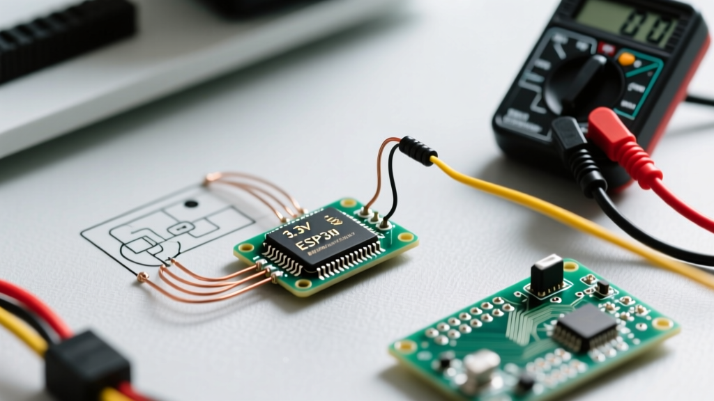
- Multimeter Continuity Check: Verify no short circuits exist between VIN and GND on the motor controller with the battery disconnected.
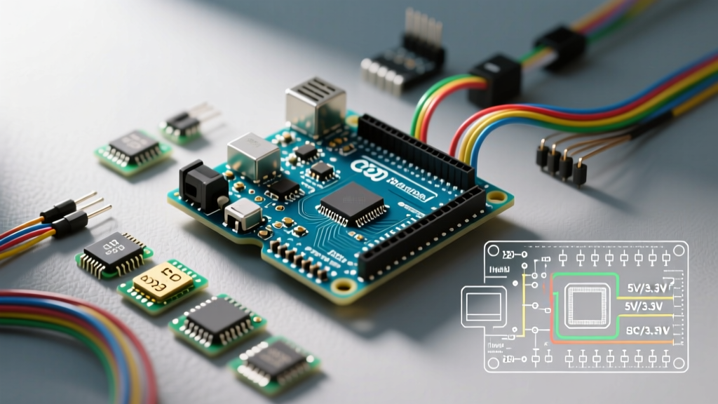
- Logic Level Verification: Confirm that the motor controller's logic VCC is receiving exactly 5.0V (or 3.3V for ESP32/RP2040 workflows) from the Arduino, not the raw battery voltage.
- PWM Frequency Validation: Use an oscilloscope or a cheap logic analyzer to verify your Timer1 registers are outputting the expected 31kHz signal, rather than the default 490Hz.
- Decoupling Inspection: Visually confirm that the 0.1µF ceramic bypass capacitor is physically located within 5mm of the driver IC's power pins.
- Directionality Test: Run a hardcoded 10% duty cycle test in both directions to verify H-bridge logic mapping before applying full torque.
By shifting your perspective from 'making the motor spin' to 'engineering a robust power and control domain,' you drastically reduce integration time. The modern motor controller Arduino workflow is about leveraging MOSFET efficiency, isolating inductive noise, and utilizing hardware-level MCU features to create robotics platforms that are quiet, responsive, and fundamentally reliable.