
The Reality of RS485 in Maker Projects
Integrating an Arduino with RS485 transceivers is the standard approach for building robust, long-distance Modbus RTU networks. While the RS-485 standard supports differential signaling over distances up to 1,200 meters, the physical layer is highly unforgiving of improper wiring, missing bias resistors, and timing errors in microcontroller firmware. Unlike simple UART connections, RS-485 requires strict adherence to bus topology, impedance matching, and direction control. When communication drops, CRC errors spike, or nodes simply refuse to respond, the root cause is almost always a physical layer violation or a firmware timing mismatch.
Hardware Anatomy: Choosing the Right Transceiver Module
Before debugging the code, verify your hardware. The ubiquitous red HW-519 module based on the MAX485 chip is fine for short breadboard tests, but it often fails in real-world deployments due to its lack of isolation and limited common-mode voltage range. Here is a breakdown of the most common TTL-to-RS485 modules used with Arduino:
| Module / IC | Typical Cost (2026) | Max Speed | Isolation | Best Use Case |
|---|---|---|---|---|
| HW-519 (MAX485) | $1.50 - $2.00 | 2.5 Mbps | None | Bench testing, short indoor runs |
| XY-017 (ADM3485) | $2.50 - $3.50 | 10 Mbps | None | Higher baud rates, 3.3V logic MCUs |
| Isolated (B0505S + ADUM1201) | $6.00 - $9.00 | 1 Mbps | Galvanic | Industrial, long outdoor runs, noisy VFDs |
Top 5 Communication Failures (and Exact Fixes)
1. The Floating Bus (Missing Bias Resistors)
Symptom: The Arduino receives random garbage bytes or 'FF' hex values when no node is transmitting, triggering false Modbus CRC errors.
The Physics: When all RS-485 nodes are in receive mode (high-impedance), the differential pair (A and B) is floating. Electromagnetic interference (EMI) will induce random voltage fluctuations, which the receiver interprets as valid data start bits.
The Fix: You must install bias resistors on the Master node (and only the Master node). According to the RS-485 standard specifications, the bus must be biased to a known idle state (Logic 1). Connect a 560Ω resistor from the A line to VCC (5V) and a 560Ω resistor from the B line to GND. This guarantees a minimum 200mV differential voltage favoring the 'mark' (idle) state.
2. Signal Reflection (Missing Termination)
Symptom: Communication works at 9600 baud but fails completely at 115200 baud. Data corruption occurs specifically at the end of long cables.
The Physics: RS-485 uses a bus topology. Fast electrical edges traveling down a twisted pair will reflect off the open ends of the cable if the impedance is not matched, causing destructive interference at the receiver.
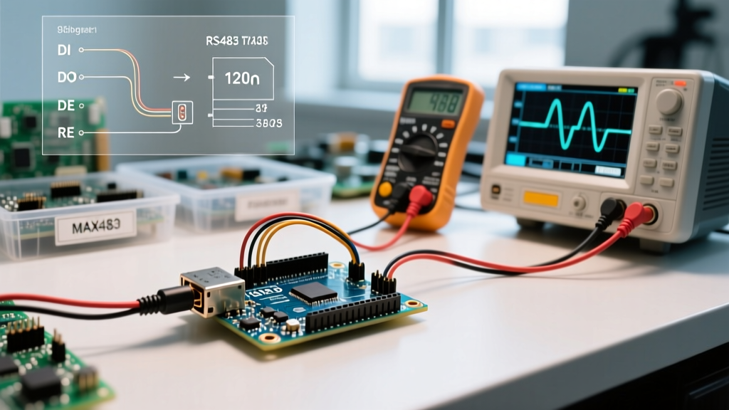
The Fix: Install a 120Ω termination resistor across the A and B lines at the first node and the last node on the physical bus. Do not place termination resistors on intermediate drop lines. Use standard CAT5e or CAT6 twisted pair cable, which inherently possesses a characteristic impedance of roughly 100-120 ohms, making 120Ω resistors the perfect match to absorb the signal energy.
3. Direction Control Timing (The DE/RE Pin Mishap)
Symptom: The Master Arduino transmits a request, but the last 1 or 2 bytes are corrupted or missing. The slave node replies with a CRC error or ignores the packet entirely.
The Physics: Most basic Arduino RS485 modules require manual control of the Driver Enable (DE) and Receiver Enable (RE) pins. A common beginner mistake is setting the DE pin LOW immediately after calling Serial.print(). However, Serial.print() only places bytes into the hardware UART TX buffer; it does not wait for the physical shift register to finish clocking out the final stop bit. Switching to RX mode too early physically cuts off the transmission.
The Fix: You must force the hardware to empty the transmit shift register before toggling the DE/RE pins. The official Arduino Serial.flush() documentation confirms this function blocks execution until the transmission completes. Your transmission block must look exactly like this:
digitalWrite(DE_RE_PIN, HIGH); // Enable TX
Serial.write(modbus_frame, frame_length);
Serial.flush(); // CRITICAL: Wait for TX shift register to empty
digitalWrite(DE_RE_PIN, LOW); // Switch back to RX
4. Ground Loop Destruction and Common-Mode Limits
Symptom: The setup works on a single desk but burns out the transceiver chip or causes total bus lockups when nodes are placed in different buildings or near heavy machinery (like Variable Frequency Drives).
The Physics: Standard MAX485 chips have a common-mode voltage limit of -7V to +12V. If the ground potential between Node A and Node B differs by more than 12V (due to ground loops or heavy inductive loads shifting local earth ground), the internal ESD protection diodes will conduct, overheat, and permanently short the IC.
The Fix: For any deployment exceeding 50 meters or crossing different AC mains circuits, abandon the HW-519. Use a galvanically isolated RS-485 module featuring a B0505S DC-DC isolator and an ADUM1201 digital isolator. Furthermore, always run a dedicated, heavy-gauge ground wire (or use the shield of a shielded twisted pair cable) tied to a single-point earth ground to drain high-frequency common-mode noise without creating a 50/60Hz ground loop.
5. Baud Rate Drift and Modbus RTU Frame Timeouts
Symptom: Intermittent Modbus timeout errors. The slave responds, but the master registers a timeout.
The Physics: Modbus RTU relies on a 3.5-character silence gap to delineate frames. If your Arduino is using the internal RC oscillator (common on ATtiny85 or bare ATmega328P chips without an external crystal), the baud rate can drift by 3-5% due to temperature changes. This drift compresses the inter-frame silence, causing the receiving UART to merge two separate Modbus frames into one invalid block.
The Fix: Always use Arduinos with external 16MHz or 8MHz quartz crystals (like the Uno, Mega, or Nano clones with the CH340G and proper crystal) for RS-485 Master nodes. If you must use an internal oscillator, restrict the baud rate to 9600 or lower, where the timing tolerance for the 3.5-character gap is wide enough to absorb the oscillator drift.
Wiring Matrix: Master vs. Node Topologies
Follow this exact checklist when terminating your physical bus to ensure compliance with Texas Instruments RS-485 design guidelines:
- Daisy Chain Only: Never use star topologies. Stub lengths (the wire from the main trunk to the transceiver) must be kept under 1 meter.
- Polarity Matters: A must connect to A (sometimes labeled D+), and B must connect to B (sometimes labeled D-). Swapping them inverts the idle state and guarantees failure.
- Shielding: If using shielded cable, connect the shield to Earth Ground at one end only (preferably the Master end) to prevent low-frequency ground loops.
- Power Supply: Do not power remote RS-485 nodes over the same long cable used for data unless you are using specialized 4-wire Modbus modules with wide-input (9-36V) DC-DC buck converters.
Summary Checklist for Field Deployment
- Verify 120Ω termination resistors are present at the extreme physical ends of the daisy chain.
- Verify 560Ω bias resistors are installed on the Master node's A and B lines.
- Confirm
Serial.flush()is called before pulling the DE/RE pin LOW in your Arduino sketch. - Measure the voltage between the GND pins of the furthest nodes with a multimeter; if it exceeds 2V AC or 5V DC, install galvanic isolation immediately.
- Use an oscilloscope or a dedicated RS-485 bus analyzer to verify the 3.5-character silence gap between Modbus frames.
By treating the physical layer with the same rigor as your firmware logic, your Arduino with RS485 network will achieve the bulletproof reliability required for industrial and outdoor automation environments.