
The 'Ghost Press' Fault: Diagnosing Switch Bounce
When designing human-machine interfaces (HMIs) or industrial limit-switch arrays with microcontrollers like the ATmega328P, ESP32, or RP2040, erratic input behavior is one of the most common field failures. You press a button once, but your serial monitor logs three distinct state changes. In error diagnosis, we classify this as a transient oscillation fault, universally known as switch bounce. If left unmitigated, this signal integrity failure will corrupt state machines, trigger unintended interrupt service routines (ISRs), and cause catastrophic actuator desync in robotics or CNC applications.
To properly debounce Arduino inputs, we must first stop treating bounce as a mere software quirk and start diagnosing it as a physical signal integrity issue. This guide provides a comprehensive diagnostic framework for isolating, measuring, and eliminating contact bounce using both hardware filtering and non-blocking software state machines.
The Physics of Mechanical Contact Bounce
When you actuate a mechanical switch, the metallic contacts (typically brass or phosphor bronze with silver or gold plating) do not mate cleanly. The kinetic energy of the moving contact causes it to physically bounce off the stationary contact multiple times before settling. During these micro-bounces, the circuit rapidly opens and closes, generating a burst of high-frequency digital noise.
The severity and duration of this bounce depend on the switch metallurgy, spring tension, and actuation force. According to extensive empirical testing documented in Jack Ganssle's A Guide to Debouncing, switch bounce can last anywhere from 100 microseconds to over 15 milliseconds. In modern MCUs operating at 16MHz to 240MHz, a 5ms bounce window equates to tens of thousands of clock cycles, allowing the microcontroller to register dozens of false triggers.
Typical Bounce Durations by Switch Type
- Omrón B3F Tactile Switches: 3ms to 8ms (highly dependent on actuation force and age).
- Cherry MX Mechanical Keyboard Switches: 1ms to 5ms (gold crosspoint contacts minimize severe bounce).
- Heavy-Duty Industrial Limit Switches: 10ms to 20ms (larger mass and heavier springs cause prolonged oscillation).
- Slide and Toggle Switches: 1ms to 3ms (wiping contact action reduces vertical bounce).
Diagnostic Step 1: Scoping the Signal
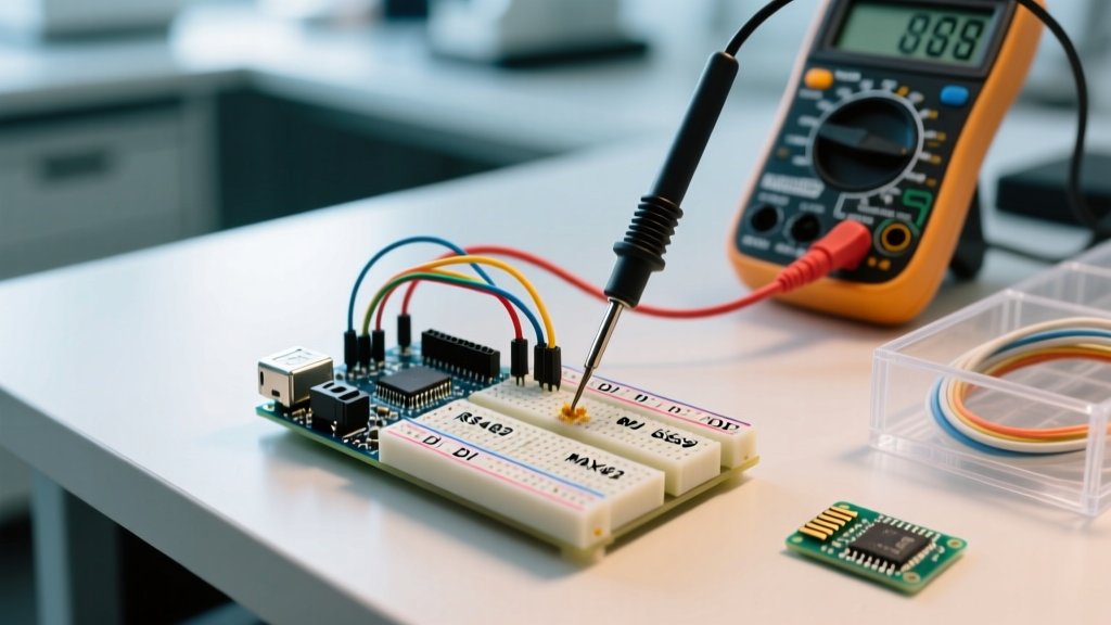
Before applying a fix, you must verify that the error is actually mechanical bounce and not electromagnetic interference (EMI). The definitive diagnostic tool is a logic analyzer or digital oscilloscope. A standard $15 Saleae Logic clone sampling at 24MHz is more than sufficient for this task.
Connect the logic analyzer probe to the MCU input pin, configure the trigger to capture on the falling edge, and actuate the switch. If you observe a chaotic, irregular burst of high-frequency pulses (often with varying duty cycles) immediately following the initial edge, you are looking at mechanical bounce. If, however, you see a perfectly periodic 50Hz or 60Hz ripple, you are diagnosing an EMI or grounding fault, not switch bounce.
Hardware Solutions: Filtering the Noise
Hardware debouncing prevents the bounce signal from ever reaching the microcontroller's GPIO pin. This is the mandatory approach for interrupt-driven inputs, as software debouncing cannot reliably prevent an ISR from being flooded by a 5ms bounce burst.
The RC Low-Pass Filter
The most cost-effective hardware fix is a passive resistor-capacitor (RC) low-pass filter. By placing a capacitor in parallel with the switch and a resistor in series with the signal line, you create a time delay that smooths out the high-frequency bounce.
Component Selection and Math:
To achieve a time constant ($\tau$) of 1ms, use a 10kΩ resistor and a 100nF (0.1µF) ceramic capacitor. Because it takes approximately $3\tau$ to $5\tau$ for the capacitor to charge or discharge sufficiently to cross the MCU's logic threshold, this configuration will effectively mask any bounce lasting up to 5ms. For heavily worn industrial switches, increase the capacitor to 470nF or 1µF.
Schmitt Trigger Hysteresis
An RC filter alone can result in slow-rising edges that make the MCU susceptible to noise. To sharpen the signal, route the RC-filtered output through a Schmitt trigger IC, such as the 74HC14 (hex inverting Schmitt trigger) or the CD40106. The hysteresis gap (typically 0.9V to 1.6V on a 5V supply) ensures that the output only transitions when the capacitor voltage definitively crosses the upper or lower threshold, completely eliminating edge chatter.
Software Solutions: Non-Blocking State Machines
For standard polling applications where hardware filtering is omitted to save board space, software debouncing is required. The novice approach is to use the delay(50) function after detecting a state change. This is a critical design flaw. Blocking the CPU for 50ms per button press destroys real-time performance and makes the system unresponsive to other sensors or communication protocols.
The Bounce2 Library Approach
The industry-standard method for software debouncing relies on a millis()-based state machine. The Bounce2 library handles this elegantly without blocking the main loop. It tracks the timestamp of the last state change and only registers a new state if the pin remains stable for a user-defined interval.
Expert Diagnostic Tip: Never set your software debounce interval lower than the physical bounce time of your specific switch. If your tactile switch bounces for 8ms, setting the Bounce2 interval to 5ms will still result in ghost presses. Always measure the worst-case bounce time with a logic analyzer and add a 20% safety margin.
Here is the diagnostic flow for implementing a robust non-blocking software debounce:
- Read the current pin state using
digitalRead(). - Compare it to the previously stored stable state.
- If the state has changed, record the current
millis()timestamp and flag the input as 'unstable'. - If the state remains unchanged, check if the time elapsed since the last transition exceeds your debounce threshold (e.g., 15ms).
- Only update the system's logical state once the threshold is met without interruption.
Comparison Matrix: Hardware vs. Software Debouncing
| Debounce Method | CPU Overhead | Pin/Board Cost | Latency | Best Use Case |
|---|---|---|---|---|
| Software (Blocking Delay) | High (Blocks CPU) | $0.00 | 50ms+ | Simple toys, basic educational kits |
| Software (Millis/Bounce2) | Negligible | $0.00 | 5ms - 20ms | Standard HMI, polling-based UI |
| Hardware (RC Filter Only) | Zero | ~$0.05 per pin | 1ms - 5ms | Low-speed inputs, cost-sensitive designs |
| Hardware (RC + Schmitt Trigger) | Zero | ~$0.35 per IC | <1ms | Interrupts, high-noise industrial environments |
Advanced Edge Cases: When Bounce Isn't Bounce
As a diagnostic technician, you will occasionally encounter 'ghost presses' that persist even after applying rigorous hardware and software debouncing. When this occurs, you are likely dealing with environmental noise masquerading as mechanical bounce.
Long Wire Runs and Capacitive Coupling
If your limit switch is connected to the Arduino via a 3-meter unshielded cable, the wire acts as an antenna. It will capacitively couple with nearby AC mains wiring, inducing 50Hz or 60Hz voltage spikes on the GPIO pin. To the MCU, this looks identical to switch bounce.
The Fix: First, use twisted-pair shielded cable (STP) for all runs exceeding 1 meter. Second, abandon the ATmega328P's internal pull-up resistors (which are typically 20kΩ to 50kΩ and far too weak for noisy environments). Install a strong external pull-up resistor—typically 1kΩ to 4.7kΩ—to lower the impedance of the signal line and shunt induced noise directly to VCC.
Ground Bounce and Power Rail Sag
Switching high-current loads (like relays or stepper motors) on the same power rail as your MCU can cause 'ground bounce.' The sudden current draw creates a voltage differential between the MCU's ground and the switch's ground, momentarily pulling the GPIO pin below the logic-low threshold. This triggers a false state change. Diagnose this by monitoring the 5V rail with an oscilloscope while actuating the load. If you see voltage sags exceeding 200mV, you must physically separate your logic and power grounds, utilizing an optocoupler (such as the PC817) to isolate the switch signal entirely.
Conclusion
Diagnosing and eliminating switch bounce requires moving beyond copy-pasted delay loops and understanding the physical and electrical realities of your hardware. By utilizing a logic analyzer to measure true bounce durations, calculating precise RC time constants, and implementing non-blocking millis() state machines via the Bounce2 library, you can guarantee absolute signal integrity in your MCU projects. Whether you are building a custom macro pad or an industrial CNC limit-switch array, rigorous debouncing is the foundation of reliable embedded systems.