
Why Your Nokia 3310 Arduino LCD Shows a Blank Screen
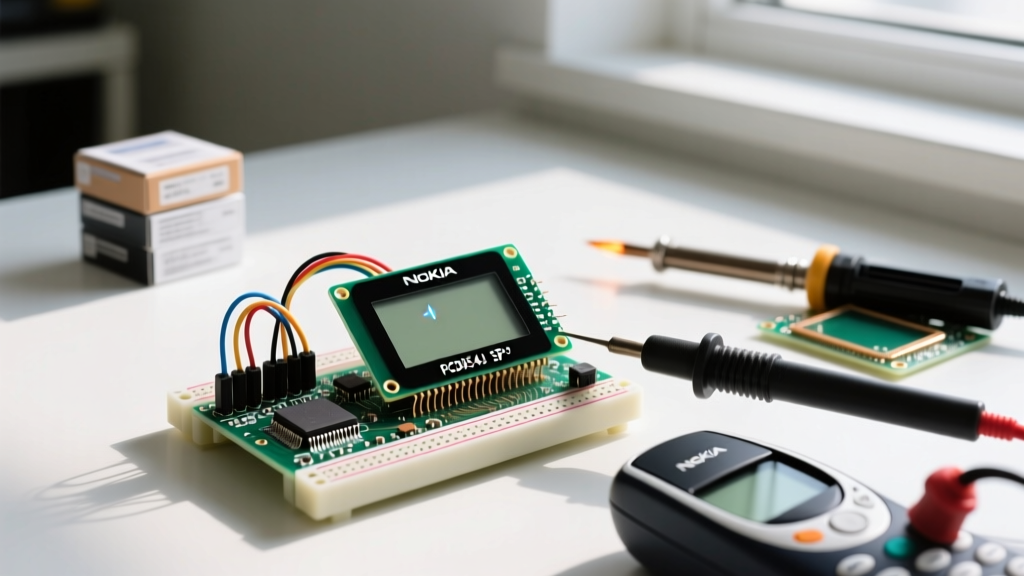
The classic Nokia 3310 LCD (along with its sibling, the Nokia 5110) remains a staple in the maker community in 2026. Driven by the ubiquitous PCD8544 controller, these 84x48 pixel monochrome displays are incredibly cheap—often costing between $1.50 and $3.00 on major electronics marketplaces. However, their low cost comes with a steep learning curve regarding voltage tolerances and SPI configuration. If you are staring at a blank, completely black, or flickering screen on your Nokia 3310 Arduino project, the issue almost always traces back to one of three failure domains: logic-level mismatch, incorrect VOP contrast register initialization, or SPI clock speed violations.
This comprehensive troubleshooting guide bypasses generic advice and dives deep into the exact hardware measurements, register hex codes, and wiring topologies required to revive your PCD8544 display and get your embedded UI rendering perfectly.
The 3.3V Logic Trap: Hardware Failure Modes
The most common reason a Nokia 3310 Arduino setup fails permanently is a logic-level mismatch. The PCD8544 controller is a 3.3V device. Its absolute maximum rating for logic inputs (DIN, CLK, CE, DC, RST) is 3.6V. If you are using a 5V Arduino Uno or Mega and wiring the digital pins directly to the display, you are pushing 5V into a 3.3V CMOS gate.
While the display might work for a few hours or even weeks, the silicon will eventually degrade due to electromigration and gate oxide breakdown, resulting in a permanently blank screen or missing pixel columns. To fix this, you must implement logic level shifting.
Proper Level Shifting Solutions
- CD4050BE Hex Buffer: The most reliable and cost-effective fix (under $0.50). Power the CD4050BE with 3.3V, feed the 5V Arduino signals into the inputs, and route the outputs to the LCD.
- BSS138 MOSFETs: Ideal for high-speed SPI lines, though slightly more complex to wire for a 5-line SPI bus.
- Voltage Dividers: Using 10kΩ and 20kΩ resistors works for low-speed I2C, but the parasitic capacitance will destroy the rising edges of a 4MHz SPI clock, causing corrupted frames. Avoid dividers for SPI.
PCD8544 Pinout and Wiring Verification
Even with level shifting, a single miswired pin will halt communication. The PCD8544 uses a 9-pin connector. Pin 1 is typically indicated by a small silk-screen dot or a red stripe on the ribbon cable. Consult the official Arduino SPI documentation to ensure your hardware SPI pins match your specific microcontroller board.
| PCD8544 Pin | Function | Arduino Uno (ATmega328P) | Notes & Warnings |
|---|---|---|---|
| 1 (RST) | Reset (Active LOW) | Digital 6 (or any GPIO) | Must be pulled HIGH after init |
| 2 (CE) | Chip Enable (Active LOW) | Digital 7 (or any GPIO) | Do not tie to GND permanently |
| 3 (DC) | Data/Command Select | Digital 5 (or any GPIO) | HIGH = Data, LOW = Command |
| 4 (DIN) | Serial Data In (MOSI) | Digital 11 (Hardware MOSI) | Requires 3.3V logic level |
| 5 (CLK) | Serial Clock (SCK) | Digital 13 (Hardware SCK) | Max 4.0 MHz clock speed |
| 6 (VCC) | Power Supply | 3.3V | Never connect to 5V |
| 7 (BL) | Backlight LED Anode | 3.3V via 100Ω Resistor | Active LOW on some clones |
| 8 (GND) | Ground | GND | Common ground with MCU |
Software Fixes: Taming the VOP Contrast Register
If your wiring is flawless and your logic levels are safe, but the screen remains blank or completely black, the issue lies in the software initialization—specifically, the VOP (Voltage Operating) register. The PCD8544 contains an internal charge pump that generates the high voltage required to bias the liquid crystals (VLCD).
According to the Adafruit PCD8544 library documentation, the contrast is set by sending a specific command byte during initialization. The formula for the LCD bias voltage is:
V_LCD = 3.06V + (VOP_decimal × 0.06V)
If the VOP value is too low, the liquid crystals won't twist, resulting in a blank (white) screen. If it is too high, the crystals over-twist, resulting in a solid black screen or permanent ghosting damage.
Finding the Contrast Sweet Spot
Most cheap clone displays manufactured in 2025 and 2026 require a VOP hex value between 0xB0 and 0xBF. Here is how to implement a dynamic contrast sweep in your setup loop to find the exact value for your specific unit:
#include <SPI.h>
#include <Adafruit_GFX.h>
#include <Adafruit_PCD8544.h>

// Software SPI (slower, but pin-flexible)
Adafruit_PCD8544 display = Adafruit_PCD8544(13, 11, 5, 7, 6);

void setup() {
  Serial.begin(9600);
  // Initialize with a baseline contrast of 0xB0 (48 decimal)
  display.begin(0xB0);
  display.clearDisplay();
  display.setTextSize(1);
  display.setTextColor(BLACK);

  // Sweep contrast to find the sweet spot
  for (int i = 0x80; i < 0xFF; i++) {
    display.setContrast(i);
    display.clearDisplay();
    display.setCursor(0,0);
    display.print("VOP: ");
    display.println(i, HEX);
    display.display();
    delay(250);
  }
}
Watch the screen as the loop runs. Note the hex value where the text is sharpest, and hardcode that value into your final display.begin() function.
Backlight Burnout and Current Limiting
A frequent mistake among beginners is wiring the Backlight (BL) pin directly to the Arduino's 5V or 3.3V pin without a current-limiting resistor. The BL pin drives a bank of surface-mount LEDs. Without a resistor, the display will draw upwards of 150mA, which can exceed the current limit of the Arduino's onboard 3.3V linear regulator (often an AMS1117-3.3 rated for 800mA max, but prone to thermal throttling).
The Fix: Always place a 100Ω to 330Ω resistor in series with the BL pin. Furthermore, be aware that on many aftermarket Nokia 3310 displays, the backlight is active LOW. This means the LED cathode is tied to the BL pin, and the anode is tied to VCC. To turn the backlight ON via software, you must set the BL GPIO pin to LOW.
Library Conflicts: Adafruit_PCD8544 vs. U8g2
When building complex UIs, the library you choose dictates memory usage and rendering speed. If you are experiencing buffer overflows or random pixel noise, you may be pushing the limits of the Arduino Uno's 2KB SRAM.
- Adafruit_PCD8544: Excellent for beginners and simple text. It allocates a 504-byte frame buffer (84 × 48 / 8). On an ATmega328P, this consumes 25% of your total SRAM, leaving little room for large strings or sensor arrays.
- U8g2: The U8g2 library is vastly superior for memory-constrained MCUs. By using the "page buffer" or "U8x8" (character-only) modes, U8g2 can render complex vector graphics and fonts using a fraction of the RAM. If your project includes an SD card module and a DHT22 sensor alongside the LCD, migrate to U8x8 to eliminate SRAM-related flickering and crashes.
Advanced Edge Cases: Flickering and Ghosting
If your display works but suffers from severe flickering or "ghosting" (faint remnants of previous frames), investigate your SPI clock speed and wire length.
The PCD8544 datasheet specifies a maximum SPI clock frequency of 4.0 MHz. By default, some modern 32-bit microcontrollers (like the ESP32 or Raspberry Pi Pico) will attempt to push SPI at 8MHz or higher. This causes the PCD8544 to drop bits, resulting in shifted rows and flickering.
Pro-Tip: If your SPI wires exceed 15cm (6 inches), parasitic capacitance will degrade the square wave of the clock signal. Keep SPI traces under 10cm, or drop the SPI clock speed to 1MHz in your library initialization settings to ensure signal integrity over longer ribbon cables.
Frequently Asked Questions
Can I use a Nokia 3310 LCD with an ESP32?
Yes, but the ESP32 operates at 3.3V logic natively, which is perfect for the PCD8544. However, the ESP32's hardware SPI pins vary by board revision. It is highly recommended to use software SPI (bit-banging) via the U8g2 library on the ESP32 to avoid pin conflicts with onboard flash memory.
Why are the colors inverted (white text on black background)?
The PCD8544 does not natively support hardware color inversion. If your screen is inverted, it is likely a software command issue. In the Adafruit library, ensure you are using display.setTextColor(BLACK, WHITE); or check if the display.invertDisplay(true); function was accidentally called in your setup loop.
My display shows only the top half of the screen. What is broken?
This indicates a failure in the internal multiplexing driver, often caused by a voltage spike on the VCC line. The PCD8544 drives the 48 rows in 6 banks of 8 pixels. If the internal row-driver silicon is damaged, it will fail to address the lower banks. This is a permanent hardware failure; the display must be replaced.